
Page 268 - Hydrogeology Principles and Practice
P. 268
HYDC07 12/5/05 5:32 PM Page 251
Groundwater pollution remediation and protection 251
BO X
Pump-and-treat system design using capture-zone type curves
7. 1
In this hypothetical example, a pump-and-treat system is under con- Following the procedure outlined in Section 7.2.1, by sup-
sideration for the restoration of an aquifer at the site of a former erimposing the single-well type curves given in Appendix 10,
sand quarry used for industrial waste disposal (Fig. 1). The site, Fig. A10.14, and moving the contour line of the plume represented
−1
which is now closed, is unlined and is known to have received drums by the 10 mgL TCE concentration towards the head of the curves,
of the organic solvent TCE for disposal at the site. Some of these the chosen type curve that encompasses the contaminant plume
drums have ruptured and monitoring wells around the site show a has a value of Q/bq = 1200 m. The result of the overlay of the type
plume of dissolved TCE contaminating the sand aquifer. The aquifer curves on to the site map is represented in Fig. 1. In performing
is confined by a clay aquitard, except where this has been removed this overlay operation, the x-axis of the type curves should be par-
by quarrying, and preliminary site investigation has revealed that allel with the direction of regional groundwater flow shown on the
the natural hydraulic gradient in the aquifer is 0.001 from east to site map.
west. A short constant-rate pumping test using a pair of monitoring The specific discharge, q, for the regional flow is calculated from
−3
2 −1
wells has yielded a value of aquifer transmissivity, T, of 10 m s Darcy’s law (see eq. 2.9) as:
−4
which gives a hydraulic conductivity value of 10 ms −1 for a
general saturated aquifer thickness, b, of 10 m in the vicinity of the q =− K h d . 0 001 10 −4 10 −7 m s −1 eq. 1
×
=
×
= 1
site. The storage coefficient, S, calculated from the pumping test l d
−4
data is 2 × 10 .
Given the above information, find the position and required pump- Now, given that Q/bq = 1200 m, then with the calculated value of
ing rate, Q, of a single extraction well to capture of the TCE plume. q and for a given aquifer thickness of 10 m, the required discharge
−1
The target clean-up standard for TCE dissolved in water is 10 mgL . rate for the extraction well is found from:
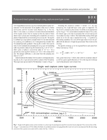
Fig. 1 Single-well capture zone curves overlain on a site map of a sand quarry used for industrial waste disposal. The contour line of the
−1
10 µgL concentration of TCE defines the limit of a pollution plume emerging from the waste site and is encompassed by the matching
position of the capture zone curve with a value of Q/bq = 1200 m.