
Page 269 - Hydrogeology Principles and Practice
P. 269
HYDC07 12/5/05 5:32 PM Page 252
252 Chapter Seven
BO X
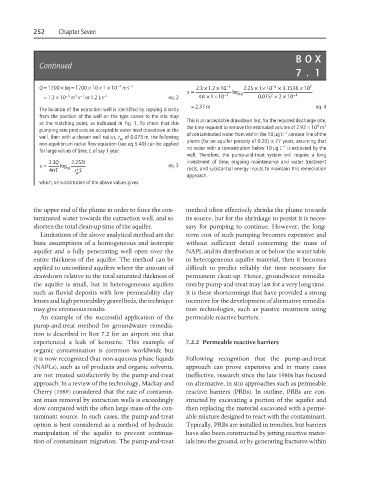
Continued
7. 1
−7
××
×
Q = 1200 × bq = 1200 × 10 × 1 × 10 ms −1 23 × 12 −3 2 25 1 −3 . 3 1536 × 10 7
. . × 10
. 10
=
s log
×
××
−3
1
3 −1
= 1.2 × 10 m s or 1.2 L s −1 eq. 2 4p 10 −3 10 . 0 075 2 × 2 10 −4
= 2.37 m eq. 4
The location of the extraction well is identified by copying directly
from the position of the well on the type curves to the site map
at the matching point, as indicated in Fig. 1. To check that this This is an acceptable drawdown but, for the required discharge rate, 3
6
pumping rate produces an acceptable water level drawdown at the the time required to remove the estimated volume of 2.92 × 10 m
−1
well, then with a chosen well radius, r , of 0.075 m, the following of contaminated water from within the 10 mgL contour line of the
w
non-equilibrium radial flow equation (see eq 5.40) can be applied plume (for an aquifer porosity of 0.20) is 77 years, assuming that
−1
for large values of time, t, of say 1 year: no water with a concentration below 10 mgL is extracted by the
well. Therefore, the pump-and-treat system will require a long
=
s . 23 Q log 10 . 225 Tt eq. 3 investment of time, ongoing maintenance and water treatment
2
4p T rS costs, and substantial energy inputs to maintain this remediation
w
approach.
which, on substitution of the above values gives:
the upper end of the plume in order to force the con- method often effectively shrinks the plume towards
taminated water towards the extraction well, and so its source, but for the shrinkage to persist it is neces-
shorten the total clean-up time of the aquifer. sary for pumping to continue. However, the long-
Limitations of the above analytical method are the term cost of such pumping becomes expensive and
basic assumptions of a homogeneous and isotropic without sufficient detail concerning the mass of
aquifer and a fully penetrating well open over the NAPL and its distribution at or below the water table
entire thickness of the aquifer. The method can be in heterogeneous aquifer material, then it becomes
applied to unconfined aquifers where the amount of difficult to predict reliably the time necessary for
drawdown relative to the total saturated thickness of permanent clean-up. Hence, groundwater remedia-
the aquifer is small, but in heterogeneous aquifers tion by pump-and-treat may last for a very long time.
such as fluvial deposits with low permeability clay It is these shortcomings that have provided a strong
lenses and high permeability gravel beds, the technique incentive for the development of alternative remedia-
may give erroneous results. tion technologies, such as passive treatment using
An example of the successful application of the permeable reactive barriers.
pump-and-treat method for groundwater remedia-
tion is described in Box 7.2 for an airport site that
experienced a leak of kerosene. This example of 7.2.2 Permeable reactive barriers
organic contamination is common worldwide but
it is now recognized that non-aqueous phase liquids Following recognition that the pump-and-treat
(NAPLs), such as oil products and organic solvents, approach can prove expensive and in many cases
are not treated satisfactorily by the pump-and-treat ineffective, research since the late 1980s has focused
approach. In a review of the technology, Mackay and on alternative, in situ approaches such as permeable
Cherry (1989) considered that the rate of contamin- reactive barriers (PRBs). In outline, PRBs are con-
ant mass removal by extraction wells is exceedingly structed by excavating a portion of the aquifer and
slow compared with the often large mass of the con- then replacing the material excavated with a perme-
taminant source. In such cases, the pump-and-treat able mixture designed to react with the contaminant.
option is best considered as a method of hydraulic Typically, PRBs are installed in trenches, but barriers
manipulation of the aquifer to prevent continua- have also been constructed by jetting reactive mater-
tion of contaminant migration. The pump-and-treat ials into the ground, or by generating fractures within