
Page 272 - Hydrogeology Principles and Practice
P. 272
HYDC07 12/5/05 5:32 PM Page 255
Groundwater pollution remediation and protection 255
an aquifer and filling the fractures with reactive ma-
terials (Hocking et al. 2000; Richardson & Nicklow
2002).
The reactive material contained in the barrier is
selected to retain the contaminant within the barrier.
PRBs containing zero-valent iron (iron filings) have
been used to treat hexavalent chromium, uranium
and technetium (Blowes et al. 2000) and chlorinated
ethenes (PCE and TCE) (O’Hannesin & Gillham
1998). Solid phase organic carbon in the form of muni-
cipal compost has been used to remove dissolved
constituents associated with acid mine drainage,
including sulphate, iron, nickel, cobalt and zinc.
Dissolved nutrients, including nitrate and phosphate,
have also been removed from domestic septic-system
effluent and agricultural drainage in this way (Blowes
et al. 2000).
In treating inorganic and organic contaminants, a
range of processes has been used such as: manipula-
tion of the redox potential to enhance biological
reductive dechlorination and to change the chemical
speciation of metals; chemical (abiotic) degradation;
precipitation; sorption to promote organic matter
partitioning and ion exchange; and biodegradation.
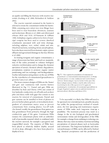
Further information and guidance on the use of PRBs Fig. 7.1 Three options for remediation of contaminated
for the remediation of contaminated groundwater is groundwater. (a) Unremediated contaminant plume. (b) Pump-
and-treat system. (c) In situ ‘continuous wall’ reactive barrier.
given by Carey et al. (2002).
(d) In situ ‘funnel and gate’ reactive barrier. In the case of the
The most common designs of PRBs are the ‘funnel funnel and gate system, a balance must be achieved between
and gate’ and ‘continuous wall’ reactive barriers maximizing the size of the capture zone for a gate and
illustrated in Fig. 7.1. Funnel and gate PRBs are maximizing the retention time of contaminated groundwater in
described by Starr and Cherry (1994) and consist of the gate. In general, capture zone size and retention time are
inversely related. After Starr and Cherry (1994).
low hydraulic conductivity cut-off walls such as sheet
piles and slurry walls with gaps that contain in situ
reactors for removal of contaminants. Funnel and
gate systems can be installed in front of plumes to To be successful, it is likely that PRBs will need to
prevent further plume growth, or immediately down- be operated over extended periods, possibly decades,
gradient of contaminant source areas to prevent but unlike the pump-and-treat method of remedi-
contaminants from creating plumes. Cut-off walls ation, the low operating and maintenance require-
(the funnel) modify the groundwater flow pattern so ments of PRBs make such long-term clean-up a
that groundwater flows primarily through the high possibility. The treatment process may result in a
conductivity gaps of the gates. Continuous PRBs change in the in situ biological and geochemical
transect the contaminant plume with an unbroken environment within and downgradient of the PRB,
wall of permeable material which is combined with for example a change from oxidizing to reducing con-
the reactive material, for example a pea-gravel and ditions, that may cause secondary reactions including
reagent-filled trench. The majority of PRBs have precipitation of mineral phases such as hydroxides
been placed at relatively shallow depths, around and carbonates. The long-term hydraulic and chem-
10–20 m deep, although a few have been placed to ical performance of PRBs can be affected by biofoul-
depths of 40 m. ing, chemical precipitation and the production of