
Page 50 - Hydrogeology Principles and Practice
P. 50
HYDC02 12/5/05 5:37 PM Page 33
Physical hydrogeology 33
ranges from a few centimetres for coarse-grained useful for determining the directions of groundwater
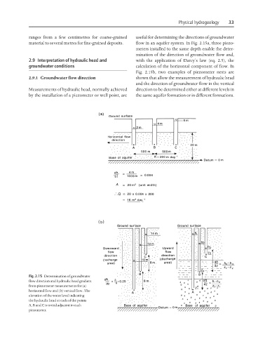
material to several metres for fine-grained deposits. flow in an aquifer system. In Fig. 2.15a, three piezo-
meters installed to the same depth enable the deter-
mination of the direction of groundwater flow and,
2.9 Interpretation of hydraulic head and with the application of Darcy’s law (eq. 2.5), the
groundwater conditions calculation of the horizontal component of flow. In
Fig. 2.15b, two examples of piezometer nests are
2.9.1 Groundwater flow direction shown that allow the measurement of hydraulic head
and the direction of groundwater flow in the vertical
Measurements of hydraulic head, normally achieved direction to be determined either at different levels in
by the installation of a piezometer or well point, are the same aquifer formation or in different formations.
Fig. 2.15 Determination of groundwater
flow direction and hydraulic head gradient
from piezometer measurements for (a)
horizontal flow and (b) vertical flow. The
elevation of the water level indicating
the hydraulic head at each of the points
A, B and C is noted adjacent to each
piezometer.