
Page 54 - Hydrogeology Principles and Practice
P. 54
HYDC02 12/5/05 5:38 PM Page 37
Physical hydrogeology 37
BO X
Continued
2.3
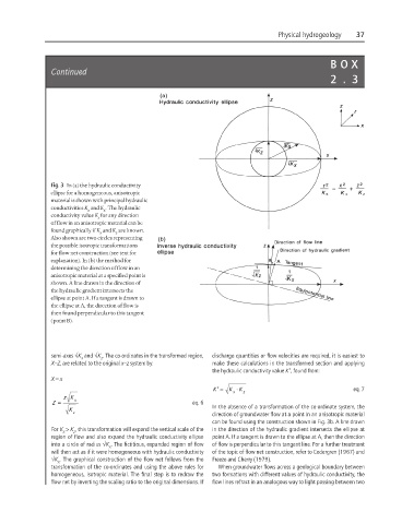
Fig. 3 In (a) the hydraulic conductivity
ellipse for a homogeneous, anisotropic
material is shown with principal hydraulic
conductivities K and K . The hydraulic
x z
conductivity value K for any direction
s
of flow in an anisotropic material can be
found graphically if K and K are known.
x z
Also shown are two circles representing
the possible isotropic transformations
for flow net construction (see text for
explanation). In (b) the method for
determining the direction of flow in an
anisotropic material at a specified point is
shown. A line drawn in the direction of
the hydraulic gradient intersects the
ellipse at point A. If a tangent is drawn to
the ellipse at A, the direction of flow is
then found perpendicular to this tangent
(point B).
semi-axes √K and √K . The co-ordinates in the transformed region, discharge quantities or flow velocities are required, it is easiest to
z
x
X–Z, are related to the original x–z system by: make these calculations in the transformed section and applying
the hydraulic conductivity value K′, found from:
X = x
K ′ = K x ⋅ K z eq. 7
zK
=
Z x eq. 6
K z In the absence of a transformation of the co-ordinate system, the
direction of groundwater flow at a point in an anisotropic material
can be found using the construction shown in Fig. 3b. A line drawn
For K > K , this transformation will expand the vertical scale of the in the direction of the hydraulic gradient intersects the ellipse at
x
z
region of flow and also expand the hydraulic conductivity ellipse point A. If a tangent is drawn to the ellipse at A, then the direction
into a circle of radius √K . The fictitious, expanded region of flow of flow is perpendicular to this tangent line. For a further treatment
x
will then act as if it were homogeneous with hydraulic conductivity of the topic of flow net construction, refer to Cedergren (1967) and
√K . The graphical construction of the flow net follows from the Freeze and Cherry (1979).
x
transformation of the co-ordinates and using the above rules for When groundwater flows across a geological boundary between
homogeneous, isotropic material. The final step is to redraw the two formations with different values of hydraulic conductivity, the
flow net by inverting the scaling ratio to the original dimensions. If flow lines refract in an analogous way to light passing between two