
Page 368 - Improving Machinery Reliability
P. 368
334 Improving Machinery Reliability
excited by small, disturbing fluid forces. In addition, the piping loops enhance the
internal fluid disturbance by creating cavities and other flow discontinuities associat-
ed with excessive pressure drops. A system similar to that shown in Figure 7-5 expe-
rienced very severe vibrations in one petrochemical plant. The responsible engineer
had to install a large cross beam anchoring all the loops in efforts to reduce vibration
to a manageable level. The function of the original loops was lost by the anchoring
system. Moreover, the piping still experienced larger than normal vibrations due to
flow disturbance caused by a loop which was now structurally fixed, but hydraulical-
ly still open to many changes in the direction of flow.
Theoretical Restraints
A properly designed piping system generally includes restraints to control the
movements and to protect sensitive equipment. However, there are also restraints
that are placed in desperation by piping engineers trying to meet the allowable load
of the equipment. These so-called computer restraints give very good computer
analysis results on paper, but are often very ineffective and sometimes even harmful.
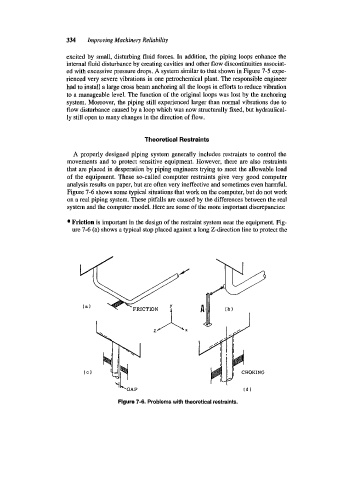
Figure 7-6 shows some typical situations that work on the computer, but do not work
on a real piping system. These pitfalls are caused by the differences between the real
system and the computer model. Here are some of the more important discrepancies:
Friction is important in the design of the restraint system near the equipment. Fig-
ure 7-6 (a) shows a typical stop placed against a long Z-direction line to protect the
Figure 7-6. Problems with theoretical restraints.