
Page 59 - Improving Machinery Reliability
P. 59
Requirements SpeciJicution 31
GAS REFERENCE
OVERHEAD
// /, // //
// // //
6-INCH (152.mm) BOTTOM OUTLET NOZZLE
- ---
DRAIN OR FILL CONNECTION
TRANSFER BARRIER
(BLADDER.TYPE)
VESSEL
VC (SEE NOTE 3)
BLAODER.LIMITER DEVICE
TO SUPPLY HEADER
(SEE NOTES 1 AN
NOW:
1. Option A.14a: If the pump is for seal oil only. Ihe purchaser may specify a switch to stop the pump.
2. Option A.14b: If pumps are lor a combined lube- and seal-oil syslem. the purchaser may specify an
alarm switch.
3. Option A-14c: The purchaser may specily an accumulator with an isvlation bladder.
4. Option A.14d:Thepurchaser may specify thedesired failure action for the loopactualedlevelcontrol
vdve.
5. The purchaser may specify a valved vent if one is available
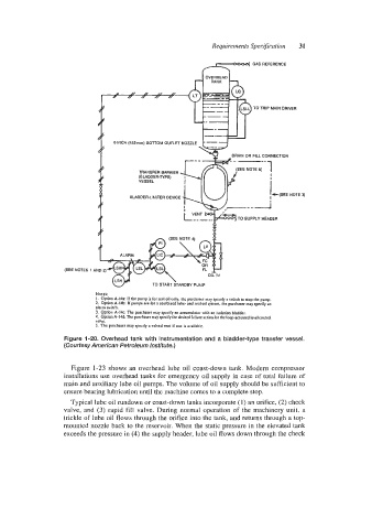
Figure 1-20. Overhead tank with instrumentation and a bladder-type transfer vessel.
(Courtesy American Petroleum Institute.)
Figure 1-23 shows an overhead lube oil coast-down tank. Modern compressor
installations use overhead tanks for emergency oil supply in case of total failure of
main and auxiliary lube oil pumps. The volume of oil supply should be sufficient to
ensure bearing lubrication until the machine comes to a complete stop.
Typical lube oil rundown or coast-down tanks incorporate (1) an orifice, (2) check
valve, and (3) rapid fill valve. During normal operation of the machinery unit, a
trickle of lube oil flows through the orifice into the tank, and returns through a top-
mounted nozzle back to the reservoir. When the static pressure in the elevated tank
exceeds the pressure in (4) the supply header, lube oil flows down through the check