
Page 57 - Improving Machinery Reliability
P. 57
Requirements Specification 29
the supply reservoir would ensure having relatively fresh, "undegraded" oil in the
accumulator at all times.
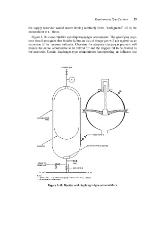
Figure 1-1 8 shows bladder and diaphragm-type accumlators. The specifying engi-
neer should recognize that bladder failure or loss of charge gas will not register as an
excursion of the pressure indicator. Checking for adequate charge-gas pressure will
require the entire accumulator to be valved off and the trapped oil to be drained to
the reservoir. Special diaphragm-type accumulators incorporating an indicator rod
CHARGE GAS
ACCUMULATOR /
TANK
BLADDER.LIMITER DEVICE
/
,
~
E
R DRAIN TO S E R V O l R 4 'ENT ~
(SEE NOTE 2)
nil niirr
NOES:
I Option A-l:ia: The purchaser may rpccily a valved vent II one is availablc.
2. The block valve is locked open.
Figure 1-18. Bladder and diaphragm-type accumulators.