
Page 53 - Improving Machinery Reliability
P. 53
Requirements Specification 25
I SLOPED DEGASIFICATION TRAY
MAXIMUM OPERATING LEVEL
I -- -- -
ALTERNATIVE ARRANGEMENT [SEE NOTE It)
PLUGGED PURGE CONNECTION
EN1 CONNECT10
FILTER-BREATHER CAP (SEE NOTE 9)
LIEF VALVE, CONTROL VAL
NDITIONER. AND OTHER
ED OIL RETURNS
SPARE
PLUGGED CONNECT1
PENING WITH STRAINER
DUAL NONPRESSURIZED
EXTERNAL-TYPE FLOAT
(SEE NOTES 121
STILLING TUBE
AND STATIC EOUALIZER
9 SIPHON BREAKER
ELECTRIC 5-
SUPPLY
PUMP SUCTION
CONNECTIONS
TWO TAPPED
GROUNDING STEAM HEATER (SEE NOTE 31 BLIND-FLANGED
PADS (SEE \ DRAIN CONNECTION
NOTE 61
'BAFFLE ATTAChED TO ST.LLlhG
TLBES AND PRESSURiZED O.L
RETURhS TO PREVEhT STlflR NG
OF BOTTOM SEO.MENTS [SEE NOTE 61
NOTES: seal-oil resewoirs, this vent shall be piped to a sale localion by Ihe
I Option A-22a: The purchaser may spcciiy a particular oil condi. purchaser.
!loner and other pressurized oil returns in addition IO the spare top 8. Individual oil relurns shall be located away from the pump suchon
connection. and arranged 10 provide the maximum residence lime
.
.
2 Option A.22b. The purchaser may speciiy an electric healer. 9. A filtcr.bredlhcr capis no1 permitied on B reservuir contdning 5rdl
3 Opiton A-22c: The purchaser may specify a steam heater. ail.
4. Option A-22d: The purchaser may specify an oil conditioner WE- IO. Purge and vcnl connections shall enter Ihe lop ')I the iexrroii
lion connection. No exlension tubcr or seals are pcrmitlcd.
5. Option A-22e. The purchaser may specify P siphon breaker when II. For nonpresrurired gravbly oil return liner. a rlilltng tube or
an oil condilioner suction conneclion is spccificd. rlopcd degasilkation m y arranged IO prcvenl splashing and provide
6. Option A-22f: When specified. lwo lapped grounding pads posi. free relcaic of luam and gar is required for cvcry return inlet and
rioned diagonally to each oiher shall be provided. spare connection.
7 A blind flange shall be provided lor venling the reservoir. Far 12. An internal-lype nodl shall be protected by a siatic-cvnducling
shield.
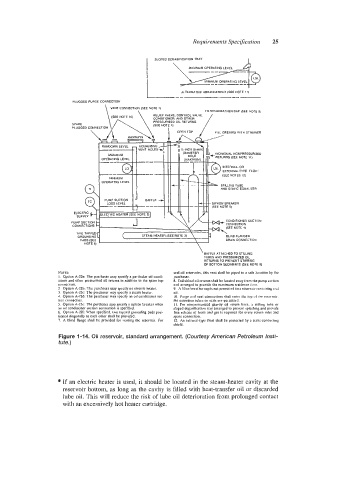
Figure 1-14. Oil reservoir, standard arrangement. (Courtesy American Petroleum Insti-
tute.)
If an electric heater is used, it should be located in the steam-heater cavity at the
reservoir bottom, as long as the cavity is filled with heat-transfer oil or discarded
lube oil. This will reduce the risk of lube oil deterioration from prolonged contact
with an excessively hot heater cartridge.