
Page 58 - Improving Machinery Reliability
P. 58
and transparent dome have been used in some installations. ‘The indicator rod is
molded into the base of the synthetic rubber diaphragm. Its position can be observed
through the transparent dome and will show the relative position of the tlinphragin.
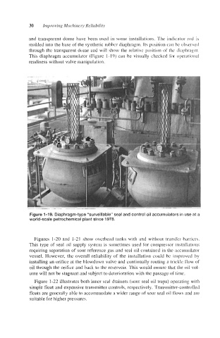
This diaphragm accumulator (Figure 1- 19) can be visually checked for operational
readiness without valve manipulation.
Figure 1-19. Diaphragm-type “surveillable” seal and control oil accumulators in use at a
world-scale petrochemical plant since 1978.
Figures 1-20 and 1-21 show overhead tanks with and without transler barriers.
This type of seal oil supply system is sometimes used for compressor installations
requiring separation of sour reference gas and seal oil contained in the accumulator
vessel. However, the overall reliability of the installation could be improved by
installing an orifice at the blowdown valve and continually routing a trickle flow of
oil through the orifice and back to the reservoir. This would ensure that the oil vol-
ume will not be stagnant and subject to deterioration with the passage of time.
Figure 1-22 illustrates both inner seal drainers (sour seal oil traps) operating with
simple float and expensive transmitter controls, respectively. Transmitter-contlollcd
floats are generally able to accommodate a wider range of sour seal oil flows and are
suitable for higher pressures.