
Page 54 - Improving Machinery Reliability
P. 54
26 hnprovirig Mcrchinery Reliability
RETURN LINES
TO RESERVOIR
MAIN STANDBY EMERGENCY
PUMP PUMP
4 4 4
f--
(SEE NOTES 7 AND 8) 4c-W AUXILIARY PUMP SUCTION
(TYPICAL: SEE NOTE 4)
(SEE NOTE 5) -
$71
PUMP SUCTION
FROM
RESERVOIR
NOTES: the main, standby. or emergency pump.
1. Option A-20a: Alarm switches arcomitled if(a) the running signal 5. Suclion V~~YCI are omitted for pumps submerged in the rc6crvotc.
is taken from the molorslarlcr or (b) an alarm swilclt is on the turbine 6. The pressure-regulating (relic0 valve is omitled lor centrilugal
driver. pumps.
2. Oplion A-20b The purchaser may specify a bypass valve to ~1~1. 7. For centrifugal pumps., Ihe line slrainers are omillcd and iempo.
3. Oplian A.2Oc: The purchaser may rpecily an emergency pump. rary screen8 are provided.
4. Oplion A-2Od: Far psilive displacement pumps. the purchaser 8. A basket-type screen shall be used instead 01 a lint slramer for the
may specify an auxiliary emergency suclion line from the reservoir 10 suction of pumps submcrged in the reservoir.
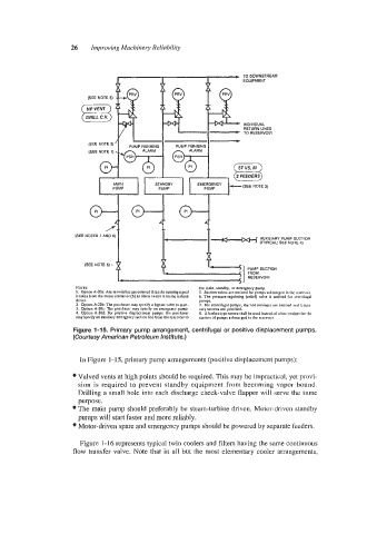
Figure 1-15. Primary pump arrangement, centrifugal or positive displacement pumps.
(Courtesy American Petroleum Institute.)
In Figure 1 - 15, primary pump arrangements (positive displacement pumps):
Valved vents at high points should be required. This may be impractical, yet provi-
sion is required to prevent standby equipment from becoming vapor bound.
Drilling a small hole into each discharge check-valve flapper will serve the same
purpose.
The main pump should preferably be steam-turbine driven. Motor-driven standby
pumps will start faster and more reliably.
Motor-driven spare and emergency pumps should be powered by separate feeders.
Figure 1-16 represents typical twin coolers and filters having the same continuous
flow transfer valve. Note that in all but the most elementary cooler arrangements,