
Page 229 - Industrial Cutting of Textile Materials
P. 229
216 Industrial Cutting of Textile Materials
(A) (B)
(C) (D)
(E) (F)
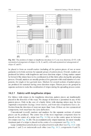
Fig. 14.1 The position of stripes in lengthwise direction (A–C), in cross direction, (D–F), with
symmetrical arrangement of stripes (A, B, D, and E), with and asymmetrical arrangement of
stripes (C and F).
be placed to form an overall marker (including all the pattern pieces of one or more
garments) or to form sections for separate groups of pattern pieces. Overall, markers are
produced for fabrics with lengthwise and cross direction stripes. A long marker cannot
be formed if the stripes have to be coordinated in all the fabric plies during the spreading
process. Overall, markers are usually produced for garments with small number of com-
ponents, for single or two garment sizes. Markers for several sections of pattern pieces
are produced for materials having cross direction stripes. Pattern pieces are grouped in
separate sections to make the coordination of stripes during the spreading process easier.
14.2.1 Fabrics with lengthwise stripes
For fabrics with stripes in the lengthwise direction, pattern pieces are traditionally
placed in the direction of the warp. No change of direction is permitted in any of the
pattern pieces. Only in the case of a faulty fabric with slanting stripes may the less
important components (facings, lower sleeves, and front-side components) have a de-
flection from the direction of warp not more than 3 mm. If there are two symmetrical
components, both must have the same deflection.
Conventional (overall) markers and markers for the separate sections of pattern
pieces can be produced. The centre line of the most important component must be
placed on the centre of a stripe (see Fig. 14.2A) or on the centre space in between
two stripes (see Fig. 14.2B). On an asymmetrically striped material, the most visually
dominant part of a stripe is placed on the centre of a component (see Fig. 14.3).
Large symmetrical pattern pieces are placed next to each other (see Fig. 14.4: com-
ponents 1 and 2) or underneath each other (see Fig. 14.5; components 4 and 5).