
Page 119 - Industrial Power Engineering and Applications Handbook
P. 119
6/100 Industrial Power Engineering and Applications Handbook
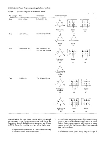
Table 6.1 Connection diagrams for multispeed motors
No. of wdgs Poles Connection Connection diagram
One 014 or 412 etc. Deltddouble star a
C b
b’
Motor winding 8-pole 4-pole
(i) (ii) (iii)
b A. b’
Two 016 or 614 etc. Staristar or deltaldelta
8-pole
6-pole
0) (ii)
Two 01614 or 61412 etc. One deltddouble star
and one star of delta
a‘
Winding no. 1 8-pole 4-pole
814-pole
0) (ii) (iii)
A
e
f Winding no. 2
6-pole
Two 121016/4 etc. Two deltddouble star
Winding no. 1 12-pole 6-pole
12/6-pole
(i) (ii) (iii)
d A
C b
e’
Winding no. 2 4-pole
8/4-pole
(iv) (vi)
control below the base speed can he achieved through 2 A continuous arcing as a result of the above, giving
the armature control at constant torque and above the rise to a source of fire hazard, particularly at instal-
base speed through the field control at constant h.p. (Figure lations that are contaminated with explosive gases,
6.7(b)). But a d.c. machine also has a few limitations: vapour or volatile liquids or are handling materials
that are hazardous.
1 Frequent maintenance due to continuously rubbing
brushes mounted on a commutator. An induction motor, particularly a squirrel cage, is