
Page 121 - Industrial Power Engineering and Applications Handbook
P. 121
6/102 Industrial Power Engineering and Applications Handbook
speed variation beyond the rated speed by sacrificing its Vlfis a concept to vary the speed, maintaining a constant
torque and maintaining the product T . f as constant. torque. Through a static drive, however, it is possible to
Since P = T . N, and N, = h, therefore speed variation vary one parameter more than the other, to obtain any
can now be achieved at constant power output (see Figure speed-torque characteristic to meet a particular duty cycle.
6.4). We have combined Figures 6.3 and 6.4 to produce By varying the rectifier and inverter parameters, a whole
Figure 6.5 for more clarity, illustrating the speed variation range of Vlfcontrol is possible. High-inertia loads, calling
at constant torque below the base speed and at constant for a slip-ring motor for a safe and smooth start, can now
h.p. above the base speed. make use of a standard squirrel cage motor. Open- or
Vlfis the most commonly used method to control the closed-loop control systems can be employed to closely
speed of a squirrel cage motor. The fixed frequency a.c. monitor and control the output voltage and frequency so
supply, say, at 415 V, 50 Hz from the mains, is first that the ratio of Vlfis always maintained constant.
rectified to a constant or variable d.c. voltage, depending
upon the static devices being used in the inverter circuit Limitations of V/f control
and their configuration. This voltage is then inverted to
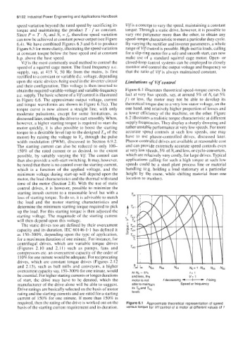
obtain the required variable-voltage and variable-frequency Figure 6.1 illustrates theoretical speed-torque curves. In
a.c. supply. The basic scheme of a Vlfcontrol is illustrated fact at very low speeds, say, at around 5% of N, (at 5%
in Figure 6.6. The approximate output voltage, current f) or less, the motor may not be able to develop its
and torque waveforms are shown in Figure 6.7(a). The theoretical torque due to a very low stator voltage, on the
torque curve is now almost a straight line, with only one hand, and relatively higher proportion of losses and
moderate pulsations, except for some limitations, as a lower efficiency of the machine, on the other. Figure
discussed later, enabling the drive to start smoothly. When, 6.2 illustrates a realistic torque characteristic at different
however, a higher starting torque is required to start the supply frequencies. They display a sharply drooping and
motor quickly, it is also possible to boost the starting rather unstable performance at very low speeds. For more
torque to a desirable level (up to the designed T,, of the accurate speed controls at such low speeds, one may
motor) by raising the voltage to V,, through the pulse have to use phasor-controlled drives, discussed later.
width modulation (PWM), discussed in Section 6.9.2. Phasor-controlled drives are available at reasonable cost
The starting current can also be reduced to only 100- and can provide extremely accurate speed controls even
150% of the rated current or as desired, to the extent at very low speeds, 5% of N, and less, or cyclo-converters,
possible, by suitably varying the Vlf. The control can which are relatively very costly, for large drives. Typical
thus also provide a soft-start switching. It may, however, applications calling for such a high torque at such low
be noted that there is no control over the starting current, speeds could be a steel plant process line or material
which is a function of the applied voltage, and the handling (e.g. holding a load stationary at a particular
minimum voltage during start-up will depend upon the height by the crane, while shifting material from one
motor, the load characteristics and the thermal withstand location to another).
time of the motor (Section 2.8). With the use of static
control drives, it is however, possible to minimize the
starting inrush current to a reasonable level but with a
loss of starting torque. To do so, it is advisable to match
the load and the motor starting characteristics and
determine the minimum starting torque required to pick
up the load. For this starting torque is then adjusted the
starting voltage. The magnitude of the starting current
will then depend upon this voltage.
The static drives too are defined by their overcurrent
capacity and its duration. EC 60146-1-1 has defined it
as 150-300%, depending upon the type of application,
for a maximum duration of one minute. For instance, for
centrifugal drives, which are variable torque drives
(Figures 2.10 and 2.1 I) such as pumps, fans and
compressors etc. an overcurrent capacity of the order of
1 10% for one minute would be adequate. For reciprocating
drives, which are constant torque drives (Figures 2.12
and 2.13), such as ball mills and conveyors, a higher
overcurrent capacity say, 15&300% for one minute, would At Ns = 5% f= 1
be essential. For higher starting currents or longer durations and less, the v= 1
of start, the drive may have to be derated, which the motor is not f decreasing f rising
manufacturer of the drive alone will be able to suggest. able to maintain Speed or frequency
Drive ratings are basically selected on the basis of motor its Tstand Tpo
rating and the starting currents and are rated for a starting levels
current of 150% for one minute. If more than 150% is
required, then the rating of the drive is worked out on the Figure 6.1 Approximate theoretical representation of speed
basis of the starting current requirement and its duration. versus torque for V/f control of a motor at different values of f