
Page 126 - Industrial Power Engineering and Applications Handbook
P. 126
Static controls and braking of motors 611 07
the drive (which we will discuss later, when discussing
drives), and the torque could be controlled directly. They
call it direct torque control (DTC).
The phasor I, and I,, are separated and then controlled
separately as discussed later. For more precise speed
control a pulse encoder feedback device can also be
employed. The characteristics now improve to Figure
6. IO. The torque can now be maintained constant at any
speed, even at zero speed.
With different approaches to monitor and control the
basic parameters of the motor, Le. I,, I, and sin 8, many
more alternatives are possible to achieve the required
speed variation in an a.c. machine. Control of these
parameters by the use of an encoder can provide an
accuracy in speed control as good as a d.c. machine and Figure 6.11 Rotor field reference frame
even better.
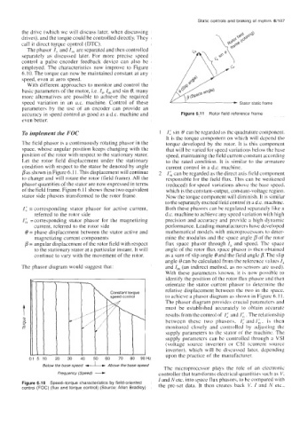
To implement the FOC 1: sin 0 can be regarded as the quadrature component.
It is the torque component on which will depend the
The field phasor is a continuously rotating phasor in the torque developed by the rotor. It is this component
space, whose angular position keeps changing with the that will be varied for speed variations below the base
position of the rotor with respect to the stationary stator. speed, maintaining the field current constant according
Let the rotor field displacement under the stationary to the rated condition. It is similar to the armature
condition with respect to the stator be denoted by angle current control in a d.c. machine.
pas shown in Figure 6.11. This displacement will continue I& can be regarded as the direct axis field component
to change and will rotate the rotor (field frame). All the responsible for the field flux. This can be weakened
phasor quantities of the stator are now expressed in terms (reduced) for speed variations above the base speed,
ofthe field frame. Figure 6.11 shows these two equivalent which is the constant-output, constant-voltage region.
stator side phasors transformed to the rotor frame. Now the torque component will diminish. It is similar
to the separately excited field control in a d.c. machine.
I; = corresponding stator phasor for active current, Both these phasors can be regulated separately like a
referred to the rotor side d.c. machine to achieve any speed variation with high
I,:, =corresponding stator phasor for the magnetizing precision and accuracy and provide a high dynamic
current, referred to the rotor side performance. Leading manufacturers have developed
8 = phase displacement between the stator active and mathematical models with microprocessors to deter-
magnetizing current components mine the modulus and the space angle p of the rotor
p = angular displacement of the rotor field with respect flux space phasor through I, and speed. The space
to the stationary stator at a particular instant. It w angle of the rotor flux space phasor is then obtained
continue to vary with the movement of the rotor as a sum of slip angle Band the field angle p. The slip
angle Bcan be calculated from the reference values I,
The phasor diagram would suggest that: and I, (an indirect method, as no sensors are used).
With these parameters known, it is now possible to
identify the position of the rotor flux phasor and then
orientate the stator current phasor to determine the
relative displacement between the two in the space.
to achieve a phasor diagram as shown in Figure 6.11.
The phasor diagram provides crucial parameters and
T must be established accurately to obtain accurate
results from the control of 1: and 16, . The relationship
e between these two phasors, It: andl,;, is then
5
co monitored closely and controlled by adjuhling the
supply parameters to the stator of the machine. The
supply parameters can be controlled through a VSI
(voltage source inverter) or CSI (current source
inverter), which will be discussed latcr, depending
Frequency (Speed) -
01 5 10 20 30 40 50 60 70 80 90Hz upon the practice of the manufacturer.
Below the base speed _I_ Above the base speed The microprocessor plays the role of an electronic
controller that transforms electrical quantities such as V.
I and N etc. into space flux phasors, to be compared with
Figure 6.1 0 Speed-torque characteristics by field-oriented the pre-set data. It then creates back V. I and N etc.,
control (FOC) (flux and torque control) (Source: Allen Bradley)