
Page 128 - Industrial Power Engineering and Applications Handbook
P. 128
Static controls and braking of motors 6/109
AC supply
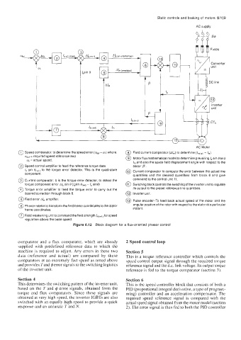
0 Speed comparator: to determine the speed error (wet- w) where, @ Field current comparator (A/,,,) to determine (/,,,c,,fi - I,,,).
q,, required speed reference and @ Motor flux mathematical model to determine prevailing I, sin 8and
=
y = actual speed.
I, and also the space field displacement angle with respect to the
@ Speed control amplifier to feed the reference torque data stator 'p'.
la sin to the torque error detector. This is the quadrature @ Current comparator to compute the error between the actual line
component. quantities and the desired quantities from block 6 and give
@ Current comparator: It is the torque error detector, to detect the command to the control unit 11.
torque component error Ala sin 8 (/,sin 8,,ef, - I, sine) @ Switching block controls the switching of the inverter unit to regulate
@ Torque error amplifier to feed the torque error to carry out the its output to the preset reference line quantities.
desired correction through block 6. @ Inverter unit.
@ Field error A/,,, amplifier.
@ Pulse encoder-To feed back actual speed of the motor and the
@ Phasor rotator to transform the field frame coordinates to the stator angular position of the rotor with respect to the stator at a particular
frame coordinates. instant.
@ Field weakening unit to command the field strength for speed
regulation above the base speed.
Figure 6.12 Block diagram for a flux-oriented phasor control
comparator and a flux comparator, which are already 2 Speed control loop
supplied with predefined reference data to which the
machine is required to adjust. Any errors in these two Section 5
data (reference and actual) are compared by these This is a torque reference controller which controls the
comparators at an extremely fast speed as noted above speed control output signal through the required torque
and provides Tand @error signals to the switching logistics reference signal and the d.c. link voltage. Its output torque
of the inverter unit. reference is fed to the torque comparator (section 3).
Section 4 Section 6
This determines the switching pattern of the inverter unit, This is the speed controller block that consists of both a
based on the T and @ error signals, obtained from the PID (proportional integral derivative, a type of program-
torque and flux comparators. Since these signals are ming) controller and an acceleration compensator. The
obtained at very high speed, the inverter IGBTs are also required speed reference signal is compared with the
switched with an equally high speed to provide a quick actual speed signal obtained from the motor model (section
response and an accurate T and N. 2). The error signal is then fed to both the PID controller