
Page 124 - Industrial Power Engineering and Applications Handbook
P. 124
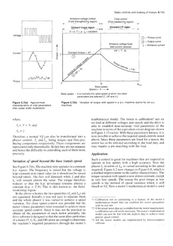
Static controls and braking of  motors  6/105
                                      -
                                      -    Consant torque region   Constant HP region   f


         Voltage
                                                            I                      1  @ =Torque curve
                                                                                     2  = Output curve
                                                                 Armature voltage fixed   I,  =Armature current
                                                                  field current reduced   I0
         Current


                                                      Speed (= f) -
         Torque
                                                            N
                                                         Base meed
                                     Base speed  - It is normally the rated speed at which the rated
                                               parameters are referred (T,, HP and V,)

         Figure 6.7(a)  Approximate   Figure 6.7(b)  Variation of torque with speed in a d.c. machine (same for an a.c.
         characteristics  of vital parameters   machine)
         after pulse width modulation


         where,                                        mathematical  model. The motor is calibration* run on
                                                       no-load at different voltages and speeds and the drive is
           I,-  T = V, and                             able to  establish  near-accurate  vital  parameters  of  the
                                                       machine in terms of the equivalent circuit diagram shown
                                                       in Figure 1.15 earlier. With these parameters known, it is
         Therefore  a  normal  Vlfsan also be transformed  into a   now possible to achieve the required speed controls noted
         phasor  control,  I, and I,  being  torque- and  flux-pro-   above. Since these parameters are fixed for a motor, the
         ducing components respectively. These components are   motor has to be selected according to the load duty and
         represented only theoretically. In fact they are not separate   may require a pre-matching with the load.
         and hence the difficulty in controlling each of them more
         precisely.                                    Application
                                                       Such a control is good for machines that are required to
         Variation of speed beyond the base (rated) speed   operate at  low  speeds with  a  high  accuracy. Now  the
         See Figure 6.7(b). The machine now operates in a constant   phasor I,, in terms off,,,,  is varied according to the speed
         h.p.  region.  The frequency is  raised but  the voltage is   required. Figure 6.2 now changes to Figure 6.8, which is
         kept constant at its rated value (as it should not be raised   a marked improvement on the earlier characteristics. The
         beyond rated). The flux will  diminish while I, and also   torque variation with speed is now almost constant, except
         I,,  will  remain  almost the  same. The torque  therefore   at very  low speeds. The reason for poor torque  at  low
         reduces  so  that  the  h.p.  developed  remains  almost  a   speeds is  the  method  of  speed  variation  which  is  still
         constant (h.p. 0~ T.W. This is also known as  the field-   based on V/f Now a motor’s mathematical model is used
         weakening region.
          In the above schemes the two quantities (I, and I,)  are
         not separated. Initially it was not easy to separate them   ______
         and the whole phasor I, was varied to achieve a  speed   *1 Calibration  run  or  autotuning  is  a  feature  of  the  motor’s
         variation. Yet close speed control was possible but  the   mathematical  model  that  can  establish  the  motor  parameterb
         motor’s basic parameters were essential to achieve more   with  its test run.
         accurate speed control. Since it may not be practical to   *2 If the actual motor data are available frnm the motor manufacturer,
                                                         a calibration run will not be necessary. The motor’s mathematical
         obtain  all  the  parameters  of  each motor promptly, the   model can now be  fed with  the explicit  data to achieve  more
         drive software is designed so that the name plate particulars   precise  speed control.
         of a motor (V, I,, Nr, and kW) alone are enough to determine   *3 All  the  motor  models  are  implemented  by  mlcrocomputer
         the machine’s required parameters through the motor’s   software.