
Page 129 - Industrial Power Engineering and Applications Handbook
P. 129
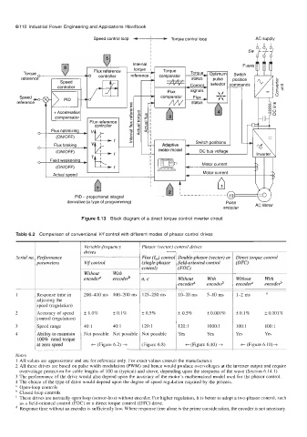
Speed control loop -
      6/11 0  Industrial Power Engineering and Applications Handbook

                                                   I  I   Torque control loop         AC supply
                                                   I


                                                                                              .-
                                                                                              c
                                                                                              c


                          PID - proportional integral
                       derivative (a type of programming)


                            Figure 6.13  Block diagram of a direct torque control inverter circuit

      Table 6.2  Comparison of conventional  V/f control with different modes of phasor control drives

                             Variable-frequency   Phasor (vector) control drives
                             drives
      Serial no  Performance                    Flux (I,,,)  control  Double-phasor (vector) or  Direct torque control
             parameters      V/f control        (single-phasor   field-oriented control   (DTC)
                                                control)    (FW
                             Without   With
                             encode?   encode#   a, c       Without   With     Without   With
                                                            encode?   encoderb   encode?   encode#
             Response time in   200-400  ms  100-200  ms  125-250  ms   10-20  ms   5-10  ms   1-2  ms   d
             adjusting the
             speed (regulation)
             Accuracy of speed  * 1.0%   * 0.1%   f 0.5%    f 0.5%    +0.001%   *0.1%    +0.001%
             control (regulation)
             Speed range     40: 1    40: 1     120:l       120:l     1000: 1   100: 1   1001
             Ability to maintain   Not possible  Not possible  Not possible   Yes   Yes   Yes   Yes
             100% rated torque
             at zero speed     t (Figure 6.2) +   (Figure 6.8)   +(Figure  6.10) +   t (Figure 6.10)+
      Notes
      1 All values are approximate and are for reference only. For exact values consult the manufacturer.
      2 All these drives are based on pulse width modulation (PWM) and hence would produce overvoltages at the inverter output and require
       overvoltage protection for cable lengths of 100 m (typical) and above, depending upon the steepness of the wave (Section 6.14.1).
      3 The performance of the drive would also depend upon the accuracy of the motor’s mathematical model used for the phasor control.
      4 The choice of the type of drive would depend upon the degree of speed regulation required by the process.
      a  Open-loop controls
       Closed-loop controls
       These drives are normally open loop (sensor-less) without encoder. For higher regulation, it is better to adopt a two-phasor control, such
       as a field-oriented control (FOC) or a direct torque control (DTC) drive.
       Response time without an encoder is sufficiently low. Where response time alone is the prime consideration, the encoder is not necessary.