
Page 134 - Industrial Power Engineering and Applications Handbook
P. 134
+
G 9
PA OA Static controls and braking of motors 6/115
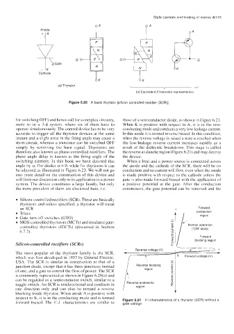
Anode PA
g Gate N K
Cathode
(a) Thyristor
(b) Equivalent 2-transistor representation
Figure 6.20 A basic thyristor [silicon controlled rectifier (SCR)]
for switching OFF) and hence call for a complex circuitry, those of a semiconductor diode, as shown in Figure 6.21.
more so in a 3-4 system, where six of them have to When K is positive with respect to A, it is in the non-
operatc simultaneously. The control device has to be very conducting mode and conducts a very low leakage current.
accurate to trigger all the thyristor devices at the same In this mode it is termed reverse biased. In this condition,
instant and a slight error in the firing angle may cause a when the reverse voltage is raised a state is reached when
short-circuit, whereas a transistor can be switched OFF the low-leakage reverse current increases rapidly as a
simply by removing the base signal. Thyristors are result of the dielectric breakdown. This stage is called
therefore also known as phase-controlled rectifiers. The the reverse avalanche region (Figure 6.2 1 ) and may destroy
phase angle delay is known as the firing angle of the the device.
switching element. In this book we have denoted this When a load and a power source is connected across
angle by a. For diodes a = 0, while for thyristors it can the anode and the cathode of the SCR, there will be no
be adjusted as illustrated in Figure 6.23. We will not go conduction and no current will flow, even when the anode
into more detail on the construction of this device and is made positive with respect to the cathode unless the
will limit our discussion only to its application in a power gate is also made forward biased with the application of
system. The device constitutes a large family, but only a positive potential at the gate. After the conduction
the more prevalent of them are discussed here, i.e. commences, the gate potential can be removed and the
Silicon-controlled rectifiers (SCR). These are basically
thyristors and unless specified, a thyristor will mean
an SCR
Triacs region
Gate turn-off switches (GTO)
MOS-controlled thyristors (MCTs) and insulated gate-
controlled thyristors (IGCTs) (discussed in Section Normal operation
(“ON” state)
6.7.2).
P Forward
5 blocking region
Silicon-controlled rectifiers (SCRs)
L J >+
,’
Reverse voltage (V)
-
The most popular of the thyristor family is the SCR, * /- F
4
which was first developed in 1957 by General Electric, f f E 1 0 Forward voltage (V)
USA. The SCR is similar in construction to that of a i \
junction diode, except that it has three junctions instead Reverse blocking a,
region
of one, and a gate to control the flow of power. The SCR -
is commonly represented as shown in Figure 6.20(a) and
can be regarded as a semiconductor switch, similar to a
toggle switch. An SCR is unidirectional and conducts in
one direction only and can also be termed a reverse
blocking triode thyristor. When anodc A is positive with
respect to K, it is in the conducting mode and is termed Figure 6.21 V-/ characteristics of a thyristor (SCR) without a
forward biased. The V-I characteristics are similar to gate voltage