
Page 138 - Industrial Power Engineering and Applications Handbook
P. 138
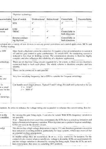
Table 6.3  A brief comparison between a transistor and basic thyristor technology

 Parameters   Transistor technology   1  Thyristor technology
 1  As a static switch   Unidirectior   Bidirectional   Controllable   Uncontrollable
                                       .-
                                 ~
                       J         -         J
                       J                   J
 uncontrollable in reverse   TRIAC   -   r‘   Controllable in
                                           both directions
 ~  ..L-l                                  both directions
 IGBT   J   -   Reverse conduct-   J       Controllable in
          ing thyristor


 ~~~~
 2  Switch OFF   This calls for no switching OFF circuitry, since a transistor can be  switched OFF   Once fired, a thyristor cannot be controlled. It requires a forced commutation to switch it
 characteristics   simply by removing the base signal.   off and the gate control is quite cumbersome. To switch OFF, the conductinp rnrrent  is
                                                               --
                                                         >
          reduced to  less than  its  holding current. The commutation circuitry  i\  therefore highly
          complex and also influences the reliability of a thyristor application.
                                  ~~~
 ~~   ~   ~__
 3  Conrrols   These require only the base signal to switch ON. Thus provide a simpler technology.   There are six thyristor firing circuits required  for a 3$ system, as there are two thyristors
          connected  back  to back  each phase. The whole  scheme is  therefore complex and  less
          reliable.
 4  For conduction ir  Generally two circuits are used   These can be connected in  anti-parallel
 both direction5
 5  Switching   Power MOSFETs and IGBTs can handle much higher switching frequencies,   Very low switching frequency, but a GTO is suitable for frequent switchings.
 frequency   compared to a thyristor. In an a.c. motor control, fast switching is mandatory  and
 therefore transistors are preferred.
          ~
 6  Rating   (a) Can handle only moderate currents and voltages. A BJT is used mostly in   Can handle much larger powers  Typical  V and I ratings for each unit dchieved so far dre
 electronic control circuits. As they are small, hundreds can be placed  on a small   V=  10kVa
 PCB (printed circuit board). Some manufacturers, however, also use them for the   I  =  3000 A”
 control of  small motors, say, up to  1615 HP.
 (b) MOSFETs and IGBTs alone are used for power applications. Rating of
 single-piece IGBT is possible up to 650 kW after considering all possible deratings.
 Typical V and I ratings for a single unit  achieved so far are
 V= 1600Va   I=2000Aa
 a Subject to applicable deratings
 These ratings can be enhanced bv connecting them in series-parallel combinations. In series to enhance the voltage rating and  in parallel  to enhance the current rating. But the
 v
 L
 controls may not be so accurate as with a single device.
 ~~~   ~~   _____~
 7  To vary V andf   Both V andfcan be varied with the help of pulse width modulation (PWM) in the   By varying the gate firing angle, V can also be varied. With SCRs frequency variation  is
 inverter circuit. The converter unit normally  is an uncontrolled power diode rectifier.   not possible.
          Note  Since an inverter is not line commutated, the SCRs have a switching limitation and
          hence a limitation in frequency variation. When thyristors are to perform frequent qwitchings,
          GTOs are used in the inverter circuit.
 -
 8  Heating effect   Low heat dissipation due to low voltage drop across the device (up to  I V only)   This device has a high voltage drop across it (up to 3 V) and therefore generates excessive
          heat and poses a cooling problem, particularly for large systems, which may even call for
          an external cooling arrangement.
 ______
 9  Cost factor   Much more economical compared to a thyristor drive in this range   In smaller ratings they are economical. In an a.c. to d.c. converter, for instance, for the
          control of a d.c. motor, where a variable d.c. voltage is desirable, SCRs are used extensively
          and the voltage variation is obtained by varying the firing angle. Since the SCRs are now
          line commutated, they pose no switching OFF problem.