
Page 133 - Industrial Power Engineering and Applications Handbook
P. 133
6/114 Industrial Power Engineering and Applications Handbook
that permits fast switching and gate voltage control and rectifier is sufficient to obtain a fixed d.c. voltage, rather
as a bipolar transistor it allows a large power handling than to use a phase-controlled thyristor rectifier to obtain
capability. The switching speed of the IGBT is also higher a variable d.c. voltage.
than that of a bipolar transistor. It thus provides an efficient However, they may generate switching surges. Although
power conversion system. With gradual and consistent moderate, they have caused failure of motor insulation
development of their design, it has been possible to achieve in some cases. Depending upon the type of installation,
higher ratings of these devices. Presently single IGBT a surge protection, in the form of dvldt protection through
units have been used to handle power up to 650 kW or chokes, may become mandatory with such drives, parti-
so. Their series-parallel combination, that initially created cularly when the cable length from the drive to the motor
limitations as a result of their complex switching, is also is too long or when the motor is rather old and may not
being overcome and it is hoped that much larger ratings possess a sound dielectric strength. More details of this
from such devices will be possible in the near future. aspect are discussed in Section 6.14.
They are used extensively in an inverter circuit to convert
a fixed d.c. supply to a variable ax. supply. Since they
are more expensive compared to power diodes, they are MOS controlled thyristors (MCTs)
not used generally in a rectifier circuit where power diodes
are mostly used. However, when the power is to be fed The latest in the field of static devices are MOS-controlled
back to the source of supply, then they are used in the thyristors (MCTs), which are a hybrid of MOSFETs and
rectifier circuit to adjust V and fof the feedback supply thyristors. There is yet another device developed in this
to that of the source. field, i.e. insulated gate-controlled thyristors (IGCTs).
With this development, thyristor technology is now Implementation of these devices in the field of static
being applied to handling large to very large power drives is in the offing.
requirements, where there is no option but to use thyristors
alone, for example, for very large motors, reactive power 6.7.3 The thyristor family
controls etc., as discussed in Section 24.10. A typical
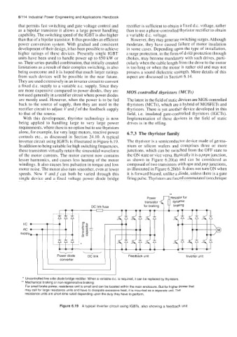
inverter circuit using IGBTs is illustrated in Figure 6.19. The thyristor is a semiconductor device made of germa-
In addition to being suitable for high switching frequencies, nium or silicon wafers and comprises three or more
these transistors virtually retain the sinusoidal waveform junctions, which can be switched from the OFF state to
of the motor currents. The motor current now contains the ON state or vice versa. Basically it is apnpn junction,
lesser harmonics, and causes less heating of the motor as shown in Figure 6.20(a) and can be considered as
windings. It also causes less pulsation in torque and low composed of two transistors with npn andpnp junctions,
motor noise. The motor also runs smoother, even at lower as illustrated in Figure 6.20(b). It does not turn ON when
speeds. Now V and f can both be varied through this it is forward biased, unlike a diode, unless there is a gate
single device and a fixed voltage power diode bridge firing pulse. Thyristors are forced commutated (a technique
Power
transistor q*iesistor dynamic for
for braking braking
* Uncontrolled line side diode bridge rectifier. When a variable d.c. is required, it can be replaced by thyristors.
*' Mechanical braking or non-regenerative braking:
For small brake power, resistance unit is small and can be located within the main enclosure. But for higher power that
may call for large resistance units and have to dissipate excessive heat, it is mounted as a separate unit. The
resistance units are short-time rated depending upon the duty they have to perform.
Figure 6.19 A typical inverter circuit using IGBTs, also showing a feedback unit