
Page 135 - Industrial Power Engineering and Applications Handbook
P. 135
6/116 Industrial Power Engineering and Applications Handbook
device will continue to conduct. It is the gate signal that Gate turn-off switches (GTOs)
plays the most vital role in achieving the desired variation
in the voltage. The main power connections to the device The gate can only turn the thyristor ON but it cannot turn
are made to its terminals A and K and a turn-on signal is it OFF (commutate). Switching OFF can be accomplished
applied between the gate and K. An SCR can easily only by reducing the conducting current to less than the
provide a variable voltage source by varying its firing thyristor's holding current. A device that allows the gate
angle. In view of its simplicity, it is the most commonly to switch OFF is called the gate turn-off switch (GTO)
used thyristor in a phase-controlled rectifier unit (con- or gate control switch (GCS). The GTO turns it OFF by
verter). Gate control is now simple, as it is connected on firing (applying) a negative potential between the gate
the a.c. or the line side, which provides it with a natural and the cathode. It is the most commonly used device in
commutation. The thyristor gets switched OFF at every a thyristor inverter circuit.
current zero. This may therefore also be termed a line
commutated rectifier.
The use of SCRs in an inverter circuit is intricate because 6.8 Conduction and commutation
of the absence of a natural commutation. Now only a
forced commutation is possible, as it is connected to a A thyristor can be turned ON by the gate at any angle a,
d.c. source which provides no current zeros and hence with respect to the applied voltage waveform as shown
facilitates no natural commutation. A forced commutation in Figure 6.23(a) and (b) for half-wave and full-wave
calls for a separate switching circuit, which is cumbersome, controlled rectifiers respectively. By varying the firing
besides adding to the cost. As a result of this feature, angle, which is possible through the firing circuit, the
they are also called forced commutated thyristors. d.c. output voltage through a converter circuit can be
varied, as illustrated in the figure. The voltage is full
Triacs (maximum) when the firing angle is zero. Now the
conduction angle is 180". As the firing angle increases,
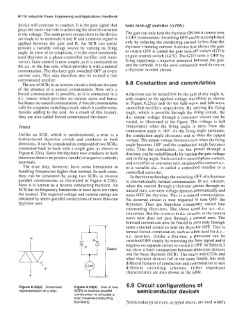
Unlike an SCR, which is unidirectional, a triac is a the conduction angle decreases and so does the output
bidirectional thyristor switch and conducts in both voltage. The output voltage becomes zero when the firing
directions. It can be considered as composed of two SCRs, angle becomes 180" and the conduction angle becomes
connected back to back with a single gate, as shown in zero. Thus the conduction, i.e. the power through a
Figure 6.22(a). Since the thyristor now conducts in both thyristor, can be varied linearly by varying the gate voltage
directions there is no positive (anode) or negative (cathode) and its firing angle. Such control is termed phase control,
terminals. and a rectifier or converter unit, employed to convert a.c.
The triac may, however, have some limitations in to a variable d.c., is called a controlled rectifier or a
handling frequencies higher than normal. In such cases, controlled converter.
they can be simulated by using two SCRs in inverse In thyristor technology the switching OFF of a thyristor
parallel combinations as illustrated in Figure 6.22(b). is conventionally termed commutation. In a.c. circuits,
Now it is known as a reverse conducting thyristor. An when the current through a thyristor passes through its
SCR has no frequency limitations at least up to ten times natural zero, a reverse voltage appears automatically and
the normal. The required voltage and current ratings are turns OFF the thyristor. This is a natural commutation.
obtained by series-parallel connections of more than one No external circuit is now required to turn OFF the
thyristor unit, thyristor. They are therefore commonly called line
commuting thyristors, like those used for a.c.-d.c.
converters. But this is not so in d.c. circuits, as the current
wave now does not pass through a natural zero. The
forward current can now be forced to zero only through
some external circuit to turn the thyristor OFF. This is
termed forced commutation, such as when used for d.c.-
a.c. inverters. Unlike a thyristor, a transistor can be
i switched OFF simply by removing the base signal and it
requires no separate circuit to switch it OFF. In Table 6.3
we show a brief comparison between transistor devices
and the basic thyristor (SCR). The triacs and GTOs and
other thyristor devices fall in the same family, but with
different features of conduction and commutation to suit
I g different switching schemes. Other important
A characteristics are also shown in the table.
6.9 Circuit configurations of
Figure 6.22(a) Schematic Figure 6.22(b) Use of two
representation of a triac SCRs in inverse parallel semiconductor devices
combination to simulate a
triac (reverse-conducting
thyristors) Semiconductor devices, as noted above, are used widely