
Page 140 - Industrial Power Engineering and Applications Handbook
P. 140
6/120 Industrial Power Engineering and Applications Handbook
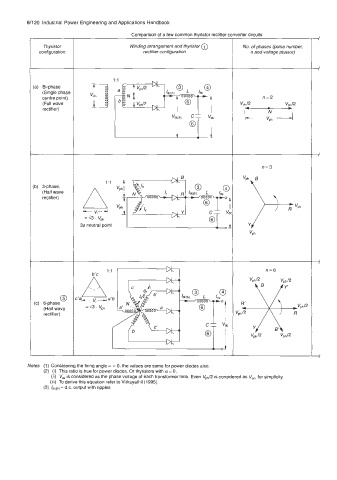
Comparison of a few common thyristor rectifier CI derter circuits
Thyristor Winding arrangement and thyristor @ No. of phases (pulse number,
configuration rectifier configuration n and voltage phasor)
(a) Bi-phase
(Single phase
centre point)
(Full wave
i n=3
rectifier)
1:l r
(b) 3-phase,
(Half wave
rectifier)
3@ neutral point
n=6
I
Notes (1) Considering the firing angle K = 0, the values are same for power diodes also.
(2) (i) This ratio is true for power diodes. Or thyristors with a= 0,
(ii) V, is considered as the phase voltage of each transformer limb. Even Vph/2 is considered as V,,, for simplicity.
(iii) To derive this equation refer to Vithayathil (1995).
(3) kdc(h) - d.c. output with ripples