
Page 143 - Industrial Power Engineering and Applications Handbook
P. 143
Static controls and braking of motors 61123
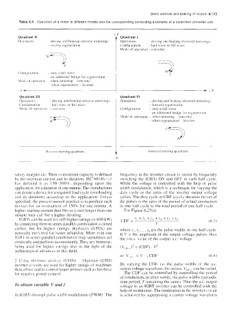
Table 6.4 Operation of a motor in different modes and the corresponding conducting quadrants of a controlled converter unit
Quadrant I1 Quadrant I
Operation\ ~ dri\ ing and braking (revme motoring) Operations - driving and braking (forward motoring)
~ ireverse regeneration Configuration - half wave or full wave
Mode of operation - converter
N7)
T
T
('onli~uratioti - onl) a full wabe 3
- an additional bridge for regeneration
Mock (it' opelation ~ when motoring ~ converter
when regenerating - inverter
)+T
Quadrant Ill Quadrant IV
Operations - dri\ tiig and braking (reverse motoring) Operations - driving and braking (forward motot-ing)
Configuration ~ half wave or full wave ~ forward regeneration
Mode of nprratim - cun\t'itet Configuration ~ only a full wave
~ an additional bridge for regeneration
Mode of operation ~ when motoring converter
~
~ when regeneration - inverter
Ke\,erse-running quadrants Forward-running quadrant\
-V
safet) margins etc. Their overcurrent capacity is defined frequency in the inverter circuit is varied by frequently
by the overload current and its duration. IEC 60146-1 -1 switching the IGBTs ON and OFF in each half cycle.
has defined it as 150-300%. depending upon the While the voltage is controlled with the help of pulse
application. for a duration of one minute. The manufacturer width modulation, which is a technique for varying the
can derate a device for a required load cycle (overloading duty cycle or the zeros of the inverter output voltage
and its duration) according to the application. IJnless pulses. The duty cycle or CDF (cyclic duration factor) of
specified. the present normal practice is to produce such the pulses is the ratio of the period of actual conduction
devices for an overcurrent of 150% for one minute. A in one half cycle to the total period of one half cycle.
himher starting current than this or a start longer than one For Figure 6.27(a)
P
minute may call for a higher derating.
t,
ICBTs can be used for still higher ratings (> 650 kW) CDF = t, f t, 4- t? + tJ -k t, i (6.3)
by connecting them in series-parallel combination as noted T
earlier. but for higher ratings, thyristors (GTOs) are where t,, t2, ... t6 are the pulse widths in one half cycle.
normally preferred for better reliability. More than one If V is the amplitude of the output voltage pulses. then
IGBT in series-parallel combination may sometimes act the r.m.s. value of the output a.c. voltage
erratically and perform inconsistently. They are, however,
being used for higher ratings also in the light of the
technological advances in this field.
or V, = V. ,/CDF (6.4)
2 C/.iirig rhyvistor- dc,ixic.e.v (GTOs) Thyristor (GTO)
inverter circuits are used for higher ratings of machines By varying the CDF, Le. the pulse widths of the ax.
than above and to control larger powers such as for those output voltage waveform, the output, V,,, ,, can be varied.
for reactivc power control. The CDF can be controlled by controlling the period
of conduction, in other words, the pulse widths (periodic
time period, Tremaining the same). Thus the a.c. output
To obtain variable V and J' voltage in an IGBT inverter can be controlled with thc
help of modulation. The modulation in the inverter circuit
In IGBT\ thr-oiigli prl vr bvidtli rnodulatiorz (PWM) The is achieved by superposing a carrier voltage waveform