
Page 148 - Industrial Power Engineering and Applications Handbook
P. 148
6/128 Industrial Power Engineering and Applications Handbook
it is common practice to dissipate the heat of regeneration converter unit is capable of performing both the jobs,
in this way but in larger machines it can be a substantial converting the fixed a.c. supply to a fixed or variable d.c.
drain on the useful energy, particularly when the machine voltage to control an ax. machine and during a regenerative
is called upon to perform frequent variations of speed, mode, feeding the regenerative energy back to the source
reversals or brakings. It is, therefore, advisable to conserve of supply. A separate transformer will not be necessary
this energy by feeding it to the other drives or by now, as the same IGBT circuit will act as a regenerative
transferring it back to the source of supply, which can be inverter. The switching of an IGBT is now an easy feature.
done in the following ways. The harmonics are also too low, and the p.f. can be
When controlling an ax. machine, the converter is maintained up to unity. Now the IGBT converter can be
usually a full-wave, power diode fixed-type rectifier and called a sinusoidal converter, as it will provide a near-
the Vlf is controlled through the IGBT inverter. For sinusoidal waveform of voltage and currents during a
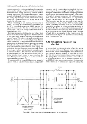
regenerative mode, the d.c. bus is connected in anti- feedback. The d.c. bus can also be made a common bus
parallel with a full-wave voltage-controlled inverter as to feed a number of drives through their individual IGBT
shown in Figure 6.3 1. inverters to cut on cost. This is possible when a number
During a regenerative braking, the d.c. voltage starts of such drives are operating in the vicinity or on the
to rise, which the inverter regulates to the required level same process line. Figure 6.33 illustrates a simple scheme
(V andf) and feeds back the regenerative energy to the with a common d.c. bus.
source of supply. This is known as synchronous inversion.
When the inverter is of a lower voltage rating than the
supply source then a transformer between this and the 6.10 Smoothing ripples in the
supply source as shown will also be necessary to regulate
the feedback voltage to the required level. The delta side d.c. link
of the transformer may be connected to the supply side
to eliminate the third harmonic quantities to the source. A power diode rectifier unit feeding a fixed d.c. power
Overvoltage, overload and short-circuit protections may to an inverter unit to control an a.c. motor, or a thyristor
be provided on the d.c. bus, on which may occur a fault rectifier unit, directly controlling a d.c. motor, both contain
or whose voltage may rise beyond the pre-set limits. A ax. ripples in their d.c. outputs, as illustrated in Figure
similar inverter circuit is used in a d.c. machine also 6.24(a). It is essential to smooth these ripples to improve
when the regenerative energy is to be fed back to the the quality of d.c. power. To achieve this, a series inductor
source of supply (Figure 6.32). L is provided in the d.c. link as shown in Figures 6.24(a)
It is also possible to use an IGBT converter instead of and 6.28(a). In the process it also reduces the harmonics
a power diode or a thyristor converter. A single IGBT on the input side. To cut on cost, it is possible to limit the
DC link
I-... I , Thyristor inverter
-
to feed energy
back to source
Dedicated transformer > in antiparallel,
to match the supply
source voltage
Figure 6.31 Regenerative energy feedback arrangement for an inverter unit