
Page 151 - Industrial Power Engineering and Applications Handbook
P. 151
Static controls and braking of motors 6/131
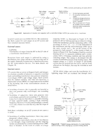
High voltage LOW current Nearly constant
and current ripples voltage L, - To limit harmonics and dddf
ripples / L - To smoothen harmonics and
/
ripples
C - To hold the charge and act as
a constant voltage source for
DC the d c machine
R - The Combination of G-Racts
as snubber circuit to protect
Switch Fuse electronic (static) components
Phase controlled from high dL/dt
variable voltage
rectifier
Figure 6.34 Application of inductor and capacitor with a controlled bridge rectifier (for control of d c machines)
on an LT system also (see IEEE-C62.41). We summarize outgoing feeder, as illustrated in Figure 6.35. the
the likely causes for such surges on an LT system and protective device will trip and trap an inductive charge
their remedial measures below. within the transformer and the connecting cables, with
an energy of 1/2 L . (1;. - is: ). L is the inductance of
External causes the transformer and the interconnecting cables up to
the static circuits and is, the cut-off current of the
- Lightning prospective fault current I,,, at the instant of fault, as
~ Transference of surges from the HV to the LV side of' shown in Figure 6.35. The clearing of fault by a current
a transformer (Section 18.5.2). limiting device is a transient condition and is synon-
ymous with a switching condition and may generate
Proteclion from such surges is achieved by using a switching surges. This energy is discharged into the
distribution class surge arrester at the receiving end of circuits located downstream of the feeding source. The
the supply. Generally no protection is therefore necessary trapped energy is a source of danger to all healthy
for the semiconductor devices. For more details see circuits that are located near the source. and the worst
Chapter 18. affected are the feeders, that may be switched at such
instants.
Internal causes
LT systems that are prone to frequent faults and outages All the above surges and even the transference of a
or constitute a number of inductive or capacitive switched lightning surge from an overhead line through inter-
loads and welding transformers may generate temporary
overvoltages (TOVs) and voltage surges. Such systems
must be studied carefully, and when felt necessary, a
metal oxide varistor (MOV) or a large inductor be installed
at the incoming side of the semiconductor circuits, as
noted below:
Switching of motors: this is generally not harmful as current) +
Current limiting
thcy can generate only overvoltages, not exceeding device
2 - v,. -3 h
Sw,itching of capacitors: these also generate only
overvoltages, generally not exceeding 2 * V,. However,
it may be ufconcern when there is a parallel switching
of large capacitor banks, causing a high switching
frequency (Section 23.5) and correspondingly a shorter
wave and ;I shorter rise time that may take the shape of
a surge. O/G feeders
Some of them may
Both the\e switchings on an LT system do not cause a state circuits
re-\tri ke
v
Suitching of welding transformers: these may cause
dangerous voltage surges. Trapped energy gets
discharged into the
0 Fault condition: particularly when the LT distribution healthy feederskircuits
IS fed through a large transformer and the outgoing
feeders are protected by a current limiting device, HRC Figure 6.35 Trapped energy distribution of a large feeding
fuses or breakers. In the event of a fault, on a large source during a fault clearing by a current-limiting device