Page 146 - Industrial Power Engineering and Applications Handbook
P. 146

6/126  Industrial Power Engineering and Applications Handbook

                                High voltage   LOW  current   ~~~~l~ constant
                                and current   ripples   voltage source
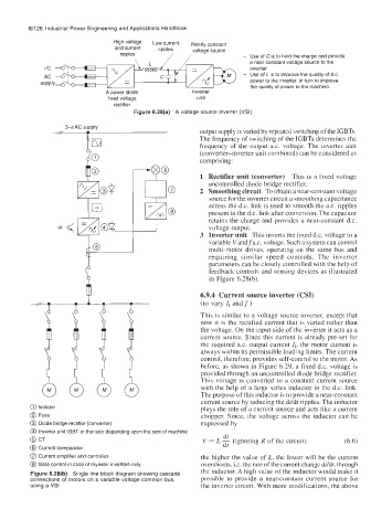
                                  ripples      //                  - Use of Cis to hold the charge and provide
                                                                     a near constant voltage source to the
                                                                     inverter
                                                                   - Use of  LIS to improve the quality of d.c.
                                                                     power to the inverter, in turn to improve
                                                                     the quality of  power to the machine.
                              A Dower diode           Inverter
                              fixed voltage            unit
                                rectifier
                                     Figure 6.28(a)  A  voltage source inverter (VSI)

                                                       output supply is varied by repeated switching of the IGBTs.
                                                       The frequency of switching of the IGBTs determines the
                                                       frequency  of  the output a.c. voltage. The inverter  unit
                                                       (converter-inverter  unit combined) can be considered as
                                                       comprising:

                                                        1  Rectifier unit (converter)  This is a fixed voltage
                                                          uncontrolled diode bridge rectifier.
                                                       2  Smoothing circuit  To obtain a near-constant voltage
                                                          source for the inverter circuit a smoothing capacitance
                                                          across the d.c. link is used to smooth the a.c. ripples
                                                          present in the d.c. link after conversion. The capacitor
                                                          retains the charge and provides  a near-constant d.c.
                                                          voltage output.
                                                        3  Inverter unit  This inverts the fixed d.c. voltage to a
                                                          variable Vandfa.c.  voltage. Such a system can control
                                                          multi-motor  drives,  operating  on  the  same bus  and
                                                          requiring  similar  speed  controls.  The  inverter
                                                          parameters can be closely controlled with the help of
                                                          feedback controls and sensing devices as illustrated
                                                          in Figure 6.28(b).

                                                        6.9.4  Current source inverter (CSI)
                                                        (to vary 1, andf)
                                                        This is similar to a voltage source inverter, except that
                                                        now it is the rectified current that is varied rather than
                                                        the voltage. On the input side of the inverter it acts as a
                                                        current source. Since this current is already pre-set for
                                                        the required  a.c.  output current I,, the motor current is
                                                        always within its permissible loading limits. The current
                                                        control, therefore, provides self-control to the motor. As
                                                        before, as shown in Figure 6.29, a fixed d.c.  voltage is
                                                        provided through an uncontrolled diode bridge rectifier.
                                                        This  voltage  is converted to a constant current  source
                                                        with the help of  a large series inductor in the d.c.  link.
                                                        The purpose of this inductor is to provide a near-constant
                                                        current source by reducing the dildt ripples. The inductor
         0 Isolator                                     plays the role of a current source and acts like a current
         @ Fuse                                         chopper. Since, the voltage  across the  inductor can be
         @ Diode bridge rectifier (converter)           expressed by
         @ Inverter unit IGBT or thyristor depending upon the size of machine
                                                              di  .
         @ CT                                           V  2-  L - (ignoring R of the circuit)   (6.6)
         @ Current comparator                                 dt
         @ Current amplifier and controller             the higher the value of L, the lower will be the current
         @ Gate control in case of thyristor inverters only.   overshoots, i.e. the rate of the current change dildt, through
                                                        the inductor. A high value of the inductor would make it
         Figure 6.28(b)  Single line block diagram showing cascade
         connections of  motors on a variable voltage common bus,   possible  to provide  a  near-constant  current  source  for
         using a VSI                                    the inverter circuit. With more modifications, the above
   141   142   143   144   145   146   147   148   149   150   151