
Page 141 - Industrial Power Engineering and Applications Handbook
P. 141
Static controls and braking of motors 6/121
Output voltage with ?atio of d.c.to a.c
Voltage and current firing angle a Cunent on 1 a.c altage
wave forms V& = - 'urrent
42.n
fora=O
d.c. output -:yL~y x v,, sin E cos a@ peak=b wa=0
voltage a.c voltage
ripples
vdc(h)
d.c. output
voltage after
)'I, I' ,I$ smoothing
I ' ,I \\ i bc 0.9
F u
waveform I a
a b-1 I
- 2d2 c
Current output waveform. Each
phase conducting for 2d2 = 180"
j,c. output voltage
Input voltage 3e cos a
I 1 vb V, I waveform. 1.17
I I
I
I
h
2x13
Current output waveform each
phase conducting for 21d3 = 120
Idc -
3 5 cos a 1.35
6
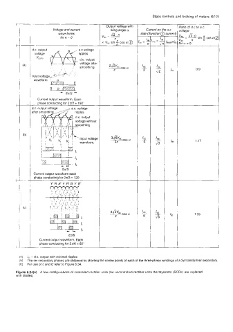
(4) IC - d.c. output with minimal ripples
(5) The six secondaly phases are obtained by shorting the centre points of each of the three-phase windings of a 36 transformer secondary.
(6) For use of L and C refer to Figure 6.34.
Figure 6.24(a) A few configurations of controlled rectifier units (for uncontrolled rectifier units the thyristors (SCRs) are replaced
with diodes)