
Page 136 - Industrial Power Engineering and Applications Handbook
P. 136
Static controls and braking of motors 611 17
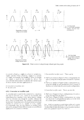
3 0 0 0 0
i'
a= 0" OL = 30" a= 60' u= 90' a= 180"
v= 0
A,!!+- /
(Y -the firing angle
60" L1 J/ @ 3-0 half wave controlled
rectifier. (Current flow-
90'
Magnitude of rectified unidirectional)
voltage can be varied
0
@
a=30 , n=60 ' , a=90" , a= 180
30" I 60" 1 v= 0
n the firing angle
@ 3-6full wave controlled
30 60" 90" rectifier (Current flow in
Magnitude of rectified both directions)
voltage can be varied
Figure 6.23 Phase control of voltage through different gate firing angles
to convert a fixed a.c. supply to a fixed or variable d.c. I Uncontrolled rectifier- units These can be
supply, and then from a fixed d.c. supply to a variable
ax. supply. for example, for variable ax. drives. A variable Half wave similar to Figure 6.24(a) configurations (b)
d.c. supply is used for the variable d.c. drives. The and (c), using one diode per phase instead ofa thyristor.
conventional nomenclature to identify the various types or
of these circuits and their applications is Full wave similar to Figure 6.24(a) configuration (a),
using two diodes in anti-parallel per phase instead of
Conberter or rectifier unit thyristors or in the form of a centre-point configuration.
Inverter unit
2 Controlled rectifier umrr These can also be
6.9.1 Converter or rectifier unit
A converter unit is used for the control of d.c. machines Half wave (Figure 6.24(a)). configurations (b) and (c)
and also to provide a d.c. source to an inverter unit using one thyristor per phase or
controlling an ax. machine. In d.c. drives the d.c. voltage Full wave (Figure 6.24(a)), configuration (a), using
after the converter unit should be variable, whereas for two thyristors in anti-parallel per phase or in the form
an a.c. drive It is kept fixed. The voltage is varied by the of a centre-point configuration.
inverter unit. A converter unit is the basic power conversion
scheme to convert an a.c. supply to a d.c. supply. Note A half-wave rectifier is a single-bridge rectifier and is witable
Conventionally they are also known as rectifier units for only single-quadrant operations I or 111. A full-wa\~ rectifiei- is
and can be arranged in four different modes to suit different a double-bridge rectifier and suitable for multi-quadrant operations
applications of a motor as follows: particularly quadrant? I1 and IV. See Table 6.3.