
Page 149 - Industrial Power Engineering and Applications Handbook
P. 149
Static controls and braking of motors 61129
-6'
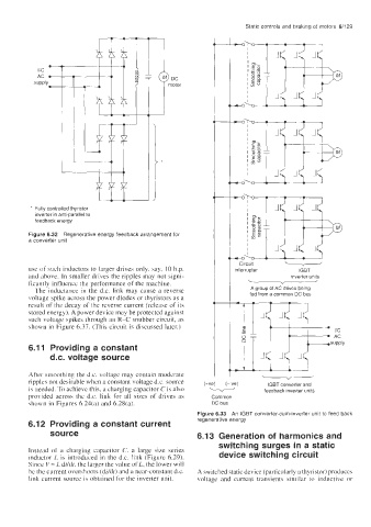
* Fully controlled thyristor
inverter in anti-parallel to
feedback energy
Figure 6.32 Regenerative energy feedback arrangement for
a converter unit Circuit -
co'
use of such inductors to larger drives only, say, IO h.p. interrupter IGBT
and above. In smaller drives the ripples may not signi- inverter units
ficantly influence the performance of the machine. u
v
~
The inductance in the d.c. link may cause a reverse A group of AC drives being
voltage spike across the power diodes or thyristors as a fed from a common DC bus
result of the decay of the reverse current (release of its
stored energy). A power device may be protected against
such voltage spikes through an R-C snubber circuit, as
shown in Figure 6.37. (This circuit is discussed later.)
6.11 Providing a constant
d.c. voltage source
After smoothing the d.c. voltage may contain moderate
ripples not desirable when a constant voltage d.c. source (+ve) (-ve) IGBT converter and
is needed. To achieve this. a charging capacitor C is also v feedback inverter units
provided across the d.c. link for all sizes of drives as Common
qhown in Figures 6.24(a) and 6.281a). DC bus
Figure 6.33 An lGBT converter-cum-inverter unit to feed back
6.12 Providing a constant current regenerative energy
source 6.13 Generation of harmonics and
switching surges in a static
Instead of a charging capacitor C, a large size series
inductor L is introduced in the d.c. link (Figure 6.29). device switching circuit
Since V = L dildt, the larger the value of L, the lower will
be the current overshoots (di/dt) and a near-constant d.c. A switched static device (particularly a thyristor) produces
link current source is obtained for the inverter unit. voltage and current transients similar to inductive or