
Page 152 - Industrial Power Engineering and Applications Handbook
P. 152
6/132 Industrial Power Engineering and Applications Handbook
L L
I/C
AC
supply
Large feeding
source
L - Inductance of the supply source
L, - Inductor to smooth ripples
1
L2- Inductor to absorb the trapped energy up to 2 L (If - &)[partly absorbed by the feeder's own impedance and other feeders
connected on the same line]
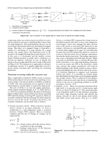
Figure 6.36 Use of inductor on the supply side of a static drive to absorb the trapped energy
connecting cables are unidirectional and reflect in ncarly During a switching OFF sequence this charge must be
full at a junction and cause a doubling effect, hence they dissipated quickly otherwise it may cause dangerous
are more dangerous. The semiconductor devices can be overvoltages, which may damage the static devices
saved from such harmful effects by absorbing the trapped used in the circuit or turn them ON when this is not
energy. The effect of a trapped charge is somewhat a wanted. A thyristor is switched ON only when there is
replica of a discharge of a surge arrester. In a surge a current pulse applied to its gate. It is possible that
arrester, the energy above the protective level of the the gate may turn ON without this pulse as a result of
arrester is discharged through the ground (Section 18.5). excessive forward duldt due to leakage capacitance
In this case, it is discharged into the healthy circuits between the thyristor junctions. The leakage capacitance
ahead. Normal practice to tackle such a situation is to may cause a charging current through the gate. When
provide an inductor, sufficient in size, to absorb this it exceeds its threshold value, it can turn the gate ON.
energy at the receiving end of the static circuit as illustrated duldt is therefore a very important limiting parameter
in Figure 6.36. This protection is applicable to all typcs to avoid an erratic turn ON of the thyristors, which
of electronic circuits. It is equally applicable even in a may corrupt the output parameters and lead to
power diode converter unit, involving no switching malfunctioning of the whole system or cause a short-
operations. circuit and damage the static devices used in the circuit.
It is therefore important to suppress such transients
Transients occurring within the converter unit within safe limits. It is possible to contain them,
provided that the stored energy can be dissipated quickly
This is applicable to thyristor (SCR) circuits to protect into another source. This is achieved by providing a
all the semiconductor dcvices used in the switching circuit, snubber circuit across each static device as noted below,
such as diodes (also power diodes) or TGBTs, in addition similar to the use of a quenching medium in an HT
to SCRs. The same protection can be applied to all the interrupter (Section 19.2).
semiconductor circuits likely to experience high duldt. Snubber circuit More conventional protection from
The role of SCRs is to vary the supply parameters, high duldt is to provide an R-C circuit across each
which require frequent changes in V, i.e. dvldt and in I, device, as shown in Figure 6.37. The circuit provides
i.e. dildt in an energized condition. Because of momentary a low impedance path to all the harmonic quantities
phase-to-phase short-circuit, duldt occurs during switching and draws large charging currents and absorbs the
OFF and dildt during switching ON sequences. Both are energy released, Q, and in turn damps duldt within
transient conditions and may damage the semiconductor safe limits across each device. Now Q = C (dvldt)
devices used in the circuit. To protect the devices, the
transient conditions can be dealt with as follows:
Voltage transients (duldt) When a thyristor switches
from a closed to an open condition, i.e. from a A
conducting to a non-conducting mode, a transient
recovery voltage (TRV) appears. This is a transient
condition and the rate of change of voltage can be It may r 1
R
expressed by
th;:&r
du or an IGBT ,.
Q=C'.-
dt
where, Q = charge stored within the devices before u
occurrence of the switching K
C' = leakage capacitance of the thyristor
between its junctions Figure 6.37 Use of a snubber circuit across a power switching
duldt = rate of rise of recovery voltage (r.r.r.v.) device