
Page 147 - Industrial Power Engineering and Applications Handbook
P. 147
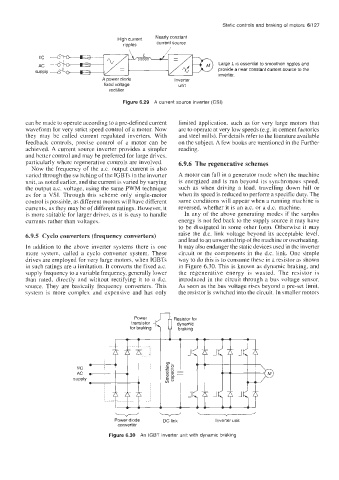
Static controls and braking of  motors 6/127


                                                                    Large L IS  essential to smoothen ripples and
                                                                   provide a near constant current source to the
                                                                   inverter.
                                A power diode         Inverter
                                 fixed voltage         unit
                                  rectifier
                                      Figure 6.29  A  current source inverter (CSI)


         can be made to operate according to a pre-defined current   limited application,  such as for very  large  motors that
         waveform for very strict speed control of a motor. Now   are to operate at very low speeds (e.g. in cement factories
         they  may  be  called  current  regulated  inverters. With   and steel mills). For details refer to the literature available
         feedback  controls,  precise  control  of  a  motor  can  be   on the subject. A few books are mentioned in the Further
         achieved. A  current source inverter provides a simpler   reading.
         and better control and may be preferred for large drives.
         particularly where regenerative controls are involved.   6.9.6  The regenerative schemes
           Now  the frequency  of  the a.c.  output current is also
         varied through the switching of the IGBTs in the inverter   A motor can fall in a generator mode when the machine
         unit, as noted earlier, and the current is varied by varying   is energized and is run  beyond  its synchronous speed,
         the output a.c. voltage, using the same PWM technique   such  as  when  driving  a  load.  travelling  down  hill  or
         as  for a  VSI. Through  this  scheme only  single-motor   when its speed is reduced to perform a specific duty. The
         control is possible, as different motors will have different   same conditions will appear when a running machine is
         currents, as they may be of different ratings. However, it   reversed, whether it is an as. or a d.c.  machine.
         is more suitable for larger drives, as it is easy to handle   In  any of the above generating modes  if  the  surplus
         currents rather than  voltages.               energy is not fed back to the supply source it may have
                                                       to be dissipated  in  some other form. Otherwise it may
         6.9.5  Cyclo converters (frequency converters)   raise  the  d.c.  link  voltage beyond  its  acceptable  level.
                                                       and lead to an unwanted trip of the machine or overheating.
         In  addition  to the  above  inverter  systems there  is one   It may also endanger the static devices used in the inverter
         more  system,  called  a  cyclo  converter  system.  These   circuit or the components in  the  d.c. link.  One simple
         drives are employed for very large motors, when IGBTs   way to do this is to consume these in a resistor as shown
         in such ratings are a limitation. It converts the fixed a.c.   in Figure 6.30. This is known as dynamic braking, and
         supply frequency to a variable frequency, generally lower   the  regenerative  energy  is  wasted.  The  resistor  is
         than  rated,  directly  and  without  rectifying  it  to  a  d.c.   introduced  in  the circuit through  a  bus  voltage sensor.
         source. They  are basically  frequency  converters.  This   As  soon as the bus voltage rises beyond a pre-set  limit,
         system  is  more  complex  and  expensive  and  has  only   the resistor is switched into the circuit. in smaller motors


                                    Power diode    DC link         Inverter unit
                                     converter
                                  Figure 6.30  An  IGBT inverter unit with dynamic braking