
Page 123 - Industrial Power Engineering and Applications Handbook
P. 123
6.4.1 Single phasor (vector) control
T- !f/f HP- Tf
Let us consider the simple equivalent motor circuit diagram
as shown earlier in Figure 1.15. The no-load component
of the current, In,, that feeds the no-load losses of the
machine contains a magnetizing component, I, . I,
produces the required magnetic field, $,, in the stator and
the rotor circuits, and develops the rotor torque so that
T .x $m . In (1.1)
The magnetizing current, I,,,, is a part of the motor stator
current Il (Figure 1.15). The rotor current is also a reflection
of the active component of this stator current, as can be
seen in the same figure, so that
Speed (f) - = I; + I, +I, (6.1)
_
_
0 Constant torque region I Constant HP region 7, = 7", + 7, _
1 -
All of these are phasor quantities. I, is the active component
responsible for developing the rotor torque and I, the
Figure 6.5 Speed control in an a.c. motor
magnetic field. Varying I, would mean a corresponding
variation in the torque developed.
While all these parameters are extremely essential for
a process line, with the R&D in the field these limitations Variation of speed below the base (rated) speed
have been overcome with the use of phasor controls. To The machine now operates in a constant torque region
implement these controls different manufacturers have (see Figure 6.7(b)). The frequency is reduced as is the
adopted different control and feedback systems to monitor voltage to maintain the same ratio of Vlf. At lower voltages,
and control the torque and field components. They have II and therefore I, will diminish, while $, and I, will
also given these controls different trade names. The basic rise, so that 4,. I, is a constant.
technological concept remains the same but process Equation (6.1) can be rewritten, for better analysis
implementation may vary from one manufacturer to with little error as
another. Below we attempt to identify the more cQmmon - -
phasor controls introduced by a few leading manufacturers. I, = I, +I,
-
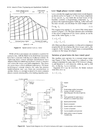
3-4a.c. supply
Fixed ax. @ Isolator
Diode bridge rectifier (converter)
Inverter unit IGBT or thyristor,
depending upon the size of machine.
CT
Tacho-generator for open loop or
encoder for a closed loop control
Speed potentiometer
Speed comparator
Speed amplifier and controller
Current comparator
Current amplifier and controller
Gate control in case of thyristor
inverters only.
3-0 Motor
(2'
Figure 6.6 Typical block diagram of a V/f control scheme with open- or closed-loop control scheme