
Page 386 - Industrial Power Engineering and Applications Handbook
P. 386
Switchgear and controlgear assemblies 13/361
17.1 I). To analyse the shape of a current wave on a short-circuit may occur somewhere between the above
short-circuit, consider the following conditions that may two conditions.
occur at the instant of the fault:
Supposing the current and the voltage waves both have
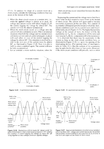
When the short-circuit occurs at a current zero, Le., some value on their respective wave forms at the instant
when the applied voltage is almost at its peak, the of short-circuit. The current will again tend to become
voltage and current waves will follow Figure 13.19, somewhat asymmetrical but not fully. The content of
the current lagging the voltage by almost 84". The asymmetry will depend upon the instant at which the short-
current will now be almost symmetrical. circuit condition occurs on the current wave and the p.f.
When the short-circuit occurs at a voltage zero the of the faulty circuit (Figure 13.27). The higher the recovery
current will also commence at zero. This is an unusual voltage at the instant of fault, the lower will be the
situation when both the voltage and the current waves asymmetry (at V,, the d.c. component will be zero) and
commence at zero and yet cannot propagate in phase vice versa (at Vo, the d.c. component will be the maximum).
with each other, in view of the current lagging the It is observed that there may be asymmetry in the
voltage by almost 84". This situation is resolved by a system as long as the short-circuit condition lasts, as
shift in the zero axis of the current wave by almost illustrated in Figure 13.20, i.e. up to the opening of the
84", as illustrated in Figure 13.26. Now it is able to interrupting device. (For opening times of interrupters,
fulfil its above condition again. The current will now refer to Table 19.1.) But the content of the asymmetry
be fully asymmetrical. may be quite feeble after three or four cycles. However,
Let us consider a more realistic situation, when the if the short-circuit condition still prevails. such as when
-.
,
Envelopes of peaks ,
EnveloDes of
axis
\ ' Envelopes of
Envelopes of peaks peaks
Figure 13.24 A symmetrical waveform Figure 13.25 An asymmetrical waveform
Shift in the Shift in the
zero axis Short circuit zero axis Short circuit
current wave
/- current wave
0
73
Healthy - Short circuit
condition ~ condition Voltage wave
I Voltage wave
Healthy-- Shorl circuit
condition I condition
Figure 13.26 Illustrating a shift of nearly 90" (drawn at 90" for Figure 13.27 Approximate illustration of a short-circuit condition
ease of illustration) in the current wave at nearly 0.1 PF, fulfilling occurring when both voltage and current waves are not at their
the condition of current lagging the voltage by nearly 90" yet natural zeros. Current shifting its zero axis from A, A2 to B, B, to
rising together at zero voltage (minimum applied voltage) rise from zero again at the instant of short-circuit