
Page 448 - Industrial Power Engineering and Applications Handbook
P. 448
14/422 Industrial Power Engineering and Applications Handbook
disturbances as well as the recommended tests and their For routine tests: class 1.0 accuracy or better, and
procedures to verify the suitability of critical structures, for type tests: not below class 0.5 accuracy.
equipment and devices for locations that are earthquake-
prone. The current transformers and potential transformers must
conform to IEC 60044-1 and IEC 60044-2 respectively.
14.2.4 Field tests Instrument transformers with the following accuracies
must be used.
Generally the following tests may be carried out at site
after installation and before energizing an assembly: For routine tests: Class 1 accuracy
For type tests: Class 0.5 accuracy
1 Checking for any human error as described in Section
14.2.2. 14.3.2 Verification of insulation resistance
2 Visual inspection of the switchgear assembly
3 Inspection of electrical wiring (see Section 14.2.2) This test is covered under field tests, Section 14.5(4).
4 Verification of insulation resistance or measurement
of the leakage current, both before and after the 14.3.3 Verification of dielectric properties
dielectric test, when an HV test is being conducted at
site. Power frequency voltage withstand or HV test
5 Verification of dielectric properties, limited to power
frequency voltage withstand test. This test is neither The test voltage must be as close to a sine wave as
mandatory nor recommended, but may be required if practicable and frequency as noted in column 3 of Tables
a modification is carried out in the switchgear assembly 14.1 and 14.2, for series I1 and Table 13.2 for series I
at site. voltage systems, and applied for one minute as follows:
1 If relays, instruments and other auxiliary apparatus,
14.3 Procedure for type tests have a voltage other than the main voltage, they should
be disconnected from the main circuit, while conduc-
Below we outline the procedure for conducting the above ting this test and tested separately, according to their
tests at the manufacturer's works. voltage rating as shown in Table 14.3.
2 All the CT (current transformer) secondaries must be
14.3.1 Electrical measurements shorted and grounded while conducting the test on
the main circuit. This condition is redundant while
Selection of testing instruments conducting test on the auxiliary circuit.
3 PT (potential transformer) windings must be disconnec-
The instruments used for electrical measurements must ted by removing the control fuses from its both sides.
conform to IEC 60051-1. Instruments with the following 4 The test voltage at the moment of application should
accuracies must be used: not exceed 50% of the rated test value and should be
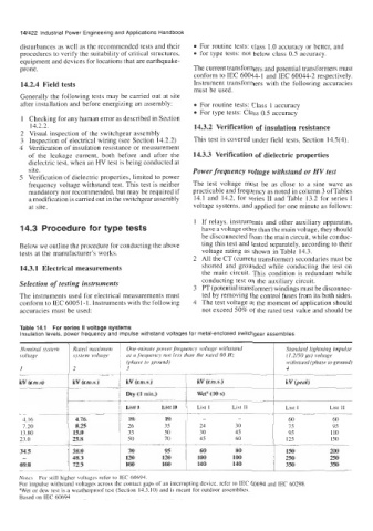
Nominal system Rated maximum One-minute power frequency voltage withstand Standard lightning impulse
voltage system voltage at a frequency not less than the rated 60 Hz (1.2/50 ,us) voltage
(phase to ground) withstand (phase to ground)
I 2 3 4
kV (r.m.s) kV (r.m.s.) kV (r.m.s.) kV (r.m.s.) kV beak)
List I List I1 List I List I1 List I List I1
4.16 4.76 19 19 - - 60 60
7.20 8.25 26 35 24 30 75 95
13.80 15.0 35 50 30 45 95 110
23.0 25.8 50 70 45 60 125 150
34.5 38.0 70 95 60 80 150 200
- 48.3 120 120 100 100 250 250
69.0 72.5 160 160 140 140 350 350