
Page 451 - Industrial Power Engineering and Applications Handbook
P. 451
Testing of metal-enclosed switchgear assemblies 14/425
Coils of the timers and totalled. This is the loss at the ambient temperature
Control fuses at the test place. It may be corrected to the operating
Coils of the measuring instruments (A, kWh and kW temperature of the assembly as shown in Table 14.5.
meters etc.) For sample calculations, we have considered it to be
Wattage of the indicating lights 90°C. Table 14.4 provides a step-by-step procedure
VA burden of the instrument and control transformers for estimation. The total watt loss of the assembly so
and Control terminals etc. determined is an estimate for the required heaters
The VA burden and the corresponding p.f. of all such that may be installed inside the assembly, to achieve
components are provided by their manufacturers. VA almost a true replica of the watt loss, as during actual
cos$ is the content of watt loss. For more details see operation. These heaters are located within the
Section 15.6.l(iii). assembly under test to circulate heat uniformly to all
3 Power connections and control wiring The loss parts to reach a rapid thermal equilibrium. To provide
within such components is measured by their resistance, heaters for individual feeders is very cumbersome
which, in the case of cables, is a function of their size and serves no purpose. The operating conditions are
and length. The loss in the external power cables is simulated similarly in the adjacent panel sections and
calculated similarly, parts of which run inside the heaters are provided there also. If the bus rating of
assembly to connect the various feeders, by measuring these sections is different from the rating of the section
their average length inside the assembly. under test, then the heating effect of these busbars
Calculating the resistance of each current-carrying should also be estimated and the rating of the heaters
component separately is a very cumbersome and altered to account for this.
lengthy procedure, in addition to being not very
accurate due to the large number of approximations. Main busbars (horizontal and vertical)
Some of the joints and components may still have
been omitted from these calculations. The easier and During the test the main busbars are fed at the rated
more often recommended procedure is to measure current, for which the switchgear assembly is designed.
the resistance between the extreme ends of each feeder They are heated naturally and therefore no resistance of
in its ON condition by an Ohm-meter. This resistance the main bus need be measured. The busbars are shorted
will also include the contact resistance of each terminal at one end and the current is fed from the other through
and joint. a variable-current injection set at a reduced voltage of
With the rating of each feeder and the resistance so 3-10 V, or enough to achieve the rated current. The
obtained, the 12R loss of each feeder can be calculated arrangement saves on power requirement and consum-
- - ~
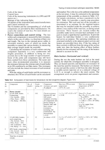
Table 14.4 Computation of heat losses for temperature rise test (single-line diagram, Figure 14.1)
S,: Component No. of Feeder Component Watt loss (PR) at room Watt loss at operating
no. feeders rating, (I) resistance per pole temperature temperature of 90°C
A R mUpole (32 "C) W, watts W, watts
(A) Power circuits
1 55 kW DOL feeder, 1 110 Circuit resistance 1 x 3 x 1 io2 x 0.33 x Since W - R and
Comprising; between I/C and = 11.98 Rgo = R32 [I + -20 (90 - 32)]
1 No. Switch - 250A OIG power :. W, at 9OoC,
3 Nos. Fuses - 200A terminals covering = W, . [I + "20(90 - 32)]
1 No. Relay - 90-50A all components and = 11.98 [l + 3.93 x 10⁻³(58)]
power wiring or = 14.71
metallic links and (xz0 for copper from
their contact Table 30.1
resistances, = 3.93 x per "c)
including end
terminations. By
measurement
= 0.33
2 5.5 kW DOL feeders, 2 12 As above = 0.52 2 x 3 x 122 x 0.52 x 10-~ 0.45 [l + 3.93 x (58)]
each comprising = 0.45 = 0.55
1 No. Switch - 63A
3 Nos. Fuses - 25A
1 No. Contactor - 16A
1 No. Relay - 9 - 14A
3 SFU feeder comprising 1 32 As above = 0.46 1 x 3 x 32'x 0.46 x 1.41[1 + 3.93 x (58)]
1 No. Switch - 63A = 1.41 = 1.73
3 Nos. Fuses - 32A
Total loss in power = 16.99 W
circuits
(Contd)