
Page 455 - Industrial Power Engineering and Applications Handbook
P. 455
Testing of metal-enclosed switchgear assemblies 14/429
3 Other parts of the switchgear assembly and the auxiliary The test conditions as noted above may over-estimate
components, for which limits have been specified, the rise in temperature during actual operation. Some
will not exceed the hot spot temperature rise, as latitude may therefore be considered while analysing the
recommended in Table 14.5. final results if the temperature rise thus estimated exceeds
the prescribed limits only marginally.
Genercrl notes on testing procedure
The main bus through its entire length is fed with its 14.3.6 Verification of short-circuit strength
rated current, while in operation it would carry a
diminishing value after every feeder or a sectional bus. This test is conducted to verify the suitability of the
The sectional bus is fed similarly. equipment to withstand a prospective short-circuit current
If a control bus is also used add for its heat loss. A that may develop on a fault. It may also be termed the
third current source may be required if a temperature steady state symmetrical fault current ISc or the short-
rise in this bus is also desired. time (withstand current) rating of the equipment. When
Keep the control circuits energized if possible, to further the equipment is an interrupting device, it is referred to
save on calculations and to obtain more accurate results. as its symmetrical breaking current.
In the sample calculations as shown in Table 14.4 we It is permissible to test just one panel of a multi panel-
consider this in a de-energized condition for the sake assembly so long as the construction of other panels
of more clarity. is similar and busbar arrangement and supports are the
Each feeder is considered at its optimum rating, based same. The value of the prospective short-circuit current
on the current rating of the motor or the rating of the may be determined from a calibrated oscillogram. The
power fuses in a SFU or FSU feeder while the current test current in any phase should not vary by more than
may be much less in actual operation. 10% of the average in the three phases and must be
If the temperature rise, as determined above. exceeds applied for a predetermined time of 1 or 3 seconds. Unless
permissible limits it will be desirable to provide extra specified otherwise, this should be considered as to be 1
louvres, a forced cooling arrangement, larger busbars or second.
a change in their configuration whichever is more The oscillogram must reveal continuity of the current
convenient and easy to implement. during the test period. The frequency of the test circuit
Q "
L
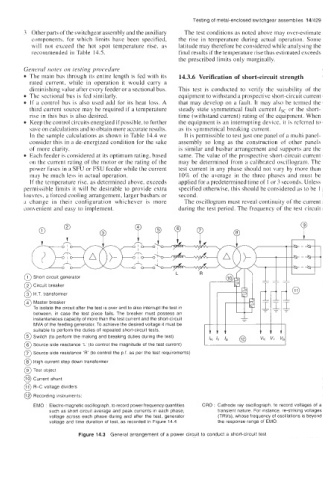
0 Short circuit generator
@ Circuit breaker
@ H.T. transformer
@ Master breaker
To isolate the circuit after the test is over and to also interrupt the test in
between, in case the test piece fails. The breaker must possess an
instantaneous capacity of more than the test current and the short-circuit
MVA of the feeding generator. To achieve the desired voltage it must be
suitable to perform the duties of repeated short-circuit tests.
@ Switch (to perform the making and breaking duties during the test)
@ Source side reactance 'L (to control the magnitude of the test current)
@ Source side resistance 'R' (to control the p.f. as per the test requirements)
@ High current step down transformer
@ Test object
@ Current shunt
@ R-C voltage dividers
@ Recording instruments:
EM0 : Electro-magnetic oscillograph, to record power frequency quantities CRO : Cathode ray oscillograph, to record voltages of a
such as short circuit average and peak currents in each phase, transient nature. For instance, re-striking voltages
voltage across each phase during and after the test, generator (TRVs), whose frequency of oscillations is beyond
voltage and time duration of test, as recorded in Figure 14.4 the response range of EMO.
Figure 14.3 General arrangement of a power circuit to conduct a short-circuit test