
Page 457 - Industrial Power Engineering and Applications Handbook
P. 457
Testing of metal-enclosed switchgear assemblies 14/431
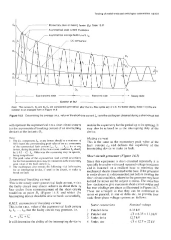
Momentary peak or making current (6), Table 13.11
Asymmetrical peak current envelopes
Asymmetrical average fault current, lav
I
fiJr
Sub-transient state
Duration of fault
Note The curves C, C2 and C3 C4 are considered symmetrical after the first few cycles say 4 to 5. For better clarity, these 4 cycles are
redrawn in an enlarged form in Figure 14.6
Figure 14.5 Determining the average r.m.s. value of the short-time current /=from the oscillogram obtained during a short-circuit test
will represent the asymmetrical r.m.s. short-circuit current sustain the asymmetry for the period up to its opening. It
(or the asymmetrical breaking current of an interrupting may also be referred to as the interrupting duty of the
device) at the instants O1. device.
Notes Making current
1 The d.c. component, Idc, at any instant should be a minimum of This is the same as the momentary peak value of the
50% that of the corresponding peak value of the a.c. component fault current INI and defines the capability of the
of the symmetrical fault current I,,,. lac,, ..., laclo, it. at any interrupting device to make on fault.
instant, during the period of the short-circuit condition, l,, should
be 2 0.5 . 42 . Iac. Otherwise the asymmetry may be ignored,
being insignificant. Short-circuit generator (Figure 14.3)
2 The peak value of the asymmetrical fault current determined
for the first maximum peak may be considered as the momentary Since this equipment is short-circuited repeatedly it is
peak value of the fault current 1~. specially braced to withstand repeated voltage transients
3 The oscillogram also reveals the following vital information and is mounted on a resilient base to minimize the
for an interrupting device, if used in the circuit, to make or mechanical shocks transmitted to the base. If the generator
break on fault;
is motor driven it is disconnected just before creating the
short-circuit condition, otherwise the generator may have
Symmetrical breaking current to feed the motor and be subject to stress. The stator has
This is the steady-state symmetrical fault current, which low reactance to give maximum short-circuit output and
the faulty circuit may almost achieve in about three or has two windings per phase as illustrated in Figure 14.7.
four cycles from commencement of the short-circuit These are arranged so that they can be connected in
condition at point DI (Figure 14.5) and which the series or parallel, in star or delta etc., to provide four
interrupting device should be able to break successfully. basic three-phase voltage systems as follows:
R.M.S. asymmetrical breaking current Stator connections Nominal voltage
This is the r.m.s. value of the asymmetrical fault current
Io, I,, ..., Zlo that the faulty circuit may generate, i.e. 1 Parallel delta 6.35 kV
ax6.35= 11.OkV
I,, = d m 2 Parallel star 12.7 kV
3 Series delta
It will determine the ability of the interrupting device to 4 Series star x 12.7 = 22 kV