Page 454 - Industrial Power Engineering and Applications Handbook
P. 454

14/428  Industrial Power Engineering and Applications Handbook
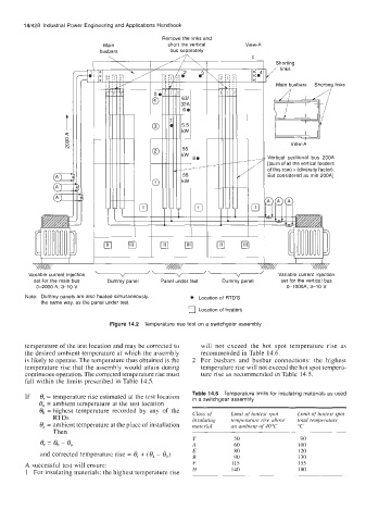
                                              Remove the links and
                              Main              short the vertical   View-A
                             busbars            bus separately         I
                                                                              Shorting

                                                                           / links
                                                                              Main busbars   Shorting links
                -1                                                         of this row) x (diversity factor).


                                                                              w

                                                                                  View-A

                                                                            Vertical  sectional  bus  200A
                                                                            [(sum of all the vertical feeders
                                                                            But considered as min 200Al


                                 c


                                                                         \
         Variable current injection   \-v-'      '  -  ;  :  \                 Variable current injection
          set for the main bus   Dummy panel   Panel under test   Dummy panel   set for the vertical bus
           0-2000  A, 3-10  V                                                    0-IOOOA,  3-10 V
        Note:  Dummy panels are also heated simultaneously,   Location of  RTD'S
            the same way,  as the panel under test
                                                      0 Location of  heaters

                                Figure 14.2  Temperature  rise test on a switchgear assembly

        temperature of the test location and may be corrected to   will  not  exceed  the  hot  spot  temperature rise  as
        the desired ambient temperature at which the assembly   recommended in Table  14.6.
        is likely to operate. The temperature thus obtained is the   2  For  busbars  and  busbar  connections: the  highest
        temperature rise that the assembly would attain during   temperature rise will not exceed the hot spot tempera-
        continuous operation. The corrected temperature rise must   ture rise as recommended in Table 14.5.
        fall within the limits prescribed in Table 14.5.
        If   8, = temperature rise estimated at the test location   Table 14.6  Temperature  limits for insulating materials as used
                                                       in a switchgear assembly
            0,  = ambient temperature at the test location
            O,, = highest  temperature  recorded  by  any  of  the
                RTDs                                   Class f3f   Limit of  hottest spot   Limit of  hottest spot
                                                                 temperature rise ubove
            8, = ambient temperature at the place of installation   insuluting   an ambient of  40 "C   total temperuture
                                                       materiul
                                                                                    "C
                Then
                                                       Y          50                 90
            8, = O,, - 8,                              A          60                100
            and corrected temperature rise = 8, + (8, - 8,)   E   80                120
                                                       B          90                130
        A successful test will ensure:                 F          I15               155
        1  For insulating materials: the highest temperature rise   H   140         180
   449   450   451   452   453   454   455   456   457   458   459