
Page 453 - Industrial Power Engineering and Applications Handbook
P. 453
Testing of metal-enclosed switchgear assemblies 14/427
Table 14.5 Temperature rise limits: for buses, bus connections and other parts of a switchgear assembly
Type of bus connection Limit of hottest spot temperature rise Limit of hottest spot total
above an ambient of 4OoC temperature
OC "C
(A) 1 For busbars and busbar connections of 50 90
aluminium or copper
2 For busbars and busbar connections of 65 105
aluminium or copper silver plated or
equivalent
3 Terminals for external insulated cables 70 110
(B) For parts exposed to contact by a human body
1 Parts handled by operator
(i) of metal 15" 55
(ii) of insulation 25 65
2 External surfaces, covers
(i) of metal 30b 70
(ii) of insulation 40 80
Note: For details of temperature rise of various parts and materials of an HT switching device refer to IEC 60694.
Based on IEC 60439-1 and 2
aPart~ that are not frequently handled, may be allowed a higher temperature rise.
bParts that are exposed but need not be touched during a normal operation, may have higher temperature rise by 25°C for metal surfaces
and 15°C for insulating surfaces.
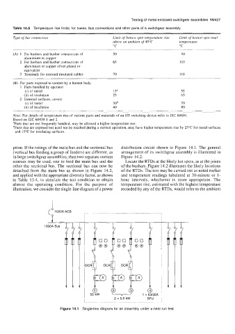
ption. If the ratings of the main bus and the sectional bus distribution circuit shown in Figure 14.1. The general
(vertical bus feeding a group of feeders) are different, as arrangement of its switchgear assembly is illustrated in
in large switchgear assemblies, then two separate current Figure 14.2.
sources may be used, one to feed the main bus and the Locate the RTDs at the likely hot spots, as at the joints
other the sectional bus. The sectional bus can now be of the busbars. Figure 14.2 illustrates the likely locations
detached from the main bus as shown in Figure 14.2, of the RTDs. The test may be carried out as noted earlier
and applied with the appropriate diversity factor, as shown and temperature readings tabulated at 30-minute or 1-
in Table 13.4, to simulate the test condition to obtain hour intervals, whichever is more appropriate. The
almost the operating condition. For the purpose of temperature rise, estimated with the highest temperature
illustration, we consider the single-line diagram of a power recorded by any of the RTDs, would refer to the ambient
Figure 14.1 Single-line diagram for an assembly under a heat run test