
Page 452 - Industrial Power Engineering and Applications Handbook
P. 452
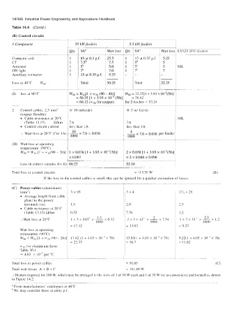
14/426  Industrial Power Engineering and Applications  Handbook
      Table 14.4  (Contd.)
      (B) Control circuits
                               1
      I  Component                55 kW feeders          5.5 kW feeders
                                    VAa         Watt loss   VA"        Watt loss1 63/32A SFUfeeders
                               I  QQ
      Contactor coil                85 at 0.3  p.f.   25.5   15 at 0.35 p.f.   5.25
      CT                            7.Sb        7.5         5b          5
      Ammeter                       5b          5.0         5b          5     NIL
      ON light                      7b          7.0         7b          7
      Auxiliary contactor           15 at 0.35 p.f.   5.25   -
      Loss at 40°C   Wd0            Total       50.25       Total      22.25

      (I)   loss at 90°C       w,,, = w,,,[ 1 + wz0 (90 - 40)1   Vgo = 22.25[1+  3.93 x 10-'(50)1
                                  = 50.25  [I + 3.93  x IO-'  (so)]   = 26.62
                                  = 60.12   for copper)   or 2 feeders = 53.24
      2   Control cables, 2.5  mm2   @  10 dfeedel      @ 5 m/  feeder
          (copper flexible).
            Cable resistance at 20°C                                          NIL
            (Table  13.15)   Rkm   7.6                  7.6
            Control circuit current   less than  IA     less than  IA
                                                            x
                                    x
                                     7.6
          :.  Watt-loss at 20°C (For 1A) ~  1 0.076     5 7.6 = 0.038  per feeder
                                        =
                                1000                     1000
      (11)  Watt loss at operating
          temperature  (90°C)
          wgo = w20 [I  4-  =20(90 - 20)]  1 x  0.076  [I  + 3.93 x  10-'(70)]   2 x 0.038 [I + 3.93 x  10-3(70)]
                               = 0.097                  = 2 x 0.048 = 0.096
          Loss in control circuits (I + 11) I 60.22     53.34                I
      Total loss in control circuits                        = 113.56 W                        (B)
                    If the loss in the control cables is small, this can be ignored for a quicker estimation of losses.
      (C)  Power cables (aluminium)
          (mm2)                 3 x  95                 3x4                    3'1,  x 25
            Average length from cable
            gland to the power
            terminals (m)       1 .5                    2.0                    2.5
            Cable resistance at 20°C
            (Table  13.15) Wkm   0.32                   7.54                   I .2
                                                                    2
                                               x
          :.Watt  loss at 20°C   1 x 3 x 110'  x 1.5 0.32   2x3~12' x-x7.54    1 x 3 x 32'  x 2.5 x 1.2
                                           1000                    1000                  1000
                                = 17.42                 = 13.03                = 9.22
          Watt loss at, operating
          temperature (90°C)
          Wg" = W2" [ 1 + -20  (90 - 20)   17.42 (1 + 4.03 x  IO-'  x  70)   13.03(1 + 4.03  x  IO-'  x 70)   9.22(1 + 4.03  x   x  70)
                                = 22.33                 = 16.7                 = 11.82
          xz0 for aluminium from
          Table 30.1
          = 4.03  x lo-'  per OC
      Total loss in power cables                        = 50.85
      Total watt losses  A + B + C                      = 181.40 W
      :.Heaters  required for 180 W, which may be arranged in the sizes of 3 of SOW each and  of 30 W (or as convenient) and located as shown
      in Figure  14.2.
      a From manufacturers'  catalogues at 4OoC
       We may consider these at unity p.f.