
Page 449 - Industrial Power Engineering and Applications Handbook
P. 449
Testing of metal-enclosed switchgear assemblies 14/423
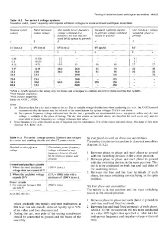
Table 14.2 For series II voltage systems
Insulation levels, power frequency and impulse withstand voltages for metal-enclosed switchgear assemblies
Nominal system Rated maximum One-minute power frequency Standard lightning impulse One-minute d.c. voltage
voltage , system voltage voltage withstand at a (1.2/50 p) voltage withstand withstand (phase to
frequency not less than the (phase to ground) ground)
rated 60 Hz (phase to ground)
I 2 3 4 5
kV (r.m.s.) kV (r.m.s)
~
b c b C b c
0.48 0.508 2.2 - - - 3.1 -
0.6 0.635 2.2 - - - 3.1 -
4.16 4.16 19.0 19 60 60 21 21
1.2a 8.25 36.0 26.0 95 75 50 31
13.8 15.0 36.0 36.0 95 95 50
14.4 1 15.5 - 50.0 - 110 IO
23.0 1 :::: - 60.0 - 125
34.5 80.0 80.0 150 150
69.0 72.5 - 160.0 - 350
aANSI C-37/20C specifies this rating only for metal-clad switchgear assemblies and not for metal-enclosed bus systems.
bWith breaker assemblies
‘With isolator assemblies
Based on ANSI C-37/20C
Notes
1 (a) The procedure for a d.c. test is same as for a.c. Due to variable voltage distributions when conducting d.c. tests, the ANSI Standard
recommends that the matter may be referred to the manufacturer for system voltages 25.8 kV and above.
(b) For a power frequency voltage withstand test, the d.c. test is generally not recommended on a.c. equipment, unless only d.c. test
voltage is available at the place of testing. The d.c. test values, as provided above, are therefore for such cases only and are
equivalent to power frequency a.c. voltage withstand test values.
2 Power frequency tests after erection at site, if required, may be conducted at 75% of the values indicated above. Also refer to field tests
(Section 14.5, Table 14.8).
Table 14.3 For series I voltage systems. Dielectric test voltages (i) For fixed as well as draw-out assemblies
for control and auxiliary circuits and also LT power circuits The trolley is in the service position in draw-out assemblies
~ ~ ~ (Section 13.3.2).
Nominal auxiliary/power One-minute power frequency
voltage voltage withstand at any
frequency between 45 and 1 Between phase to phase and each phase to ground
65 Hz (between phases and with the switching devices in the closed position
ground) 2 Between phase to phase and each phase to ground
with the switching devices in the open position. This
Control and auxiliary circuits test is to be conducted on both line and load sides of
1 Where the rated insulation 1000 V (r.m.s.) the switching device.
voltage does not exceed 60 V 3 Between the line and the load terminals of each
2 Where the insulation voltage (2 V, + 1000) volts with a phase, the main switching devices being in the open
exceeds 60 V minimum of 1500 V (r.m.s.).
position.
Power circuits
3 For voltages between 300 2500 V (rms) (ii) For draw-out assemblies
and 660 V
The trolley is in test position and the main switching
As in IEC 60439-1 device in the closed position,
1 Between phase to phase and each phase to ground on
raised gradually but rapidly and then maintained at both line and load fixed terminals.
that level for one minute, reduced rapidly up to 50% 2 Between line and load fixed terminals of each phase.
of its value and then disconnected. ANSI-C37/20C recommends this test to be conducted
5 During the test, one pole of the testing transformer at a value 10% higher than specified in Table 14.2 for
should be connected to ground and the frame of the both power frequency and impulse voltage withstand
assembly. tests.