
Page 458 - Industrial Power Engineering and Applications Handbook
P. 458
14/432 Industrial Power Engineering and Applications Handbook
Testing of the main circuits (with short-circuit
protective devices)
For a switching device (which has not been previously
tested for a short-circuit test). This should be closed
and held in the normal service position. The test voltage
(that would generate the required level of fault current)
may be applied on one set of terminals, the other
terminals being shorted. The test may be continued
until the short-circuit device operates to clear the fault,
but in no case for less than 10 cycles. In LT assemblies
4 the point where the short-circuit is created should be
2 f 0.4 m from the nearest point of supply.
For a switching device having no protection (e.g.
an Isolator). The required test current may be applied
for the necessary duration (1 or 3 seconds) and the
dynamic and thermal strengths should be verified.
For the main busbars
- In LT assemblies, when the test is conducted on
busbars, the length of busbars should be minimum
2 m. If it is less than this, short-circuit may be
created at the ends of the busbars.
- If the busbars consist of more than one section in
cross-section, or different distances between the
supports or the busbars, the test may be conducted
J Test results
separately on each section.
- A successful test should reveal no undue defor-
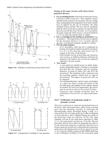
Figure 14.6 Illustration of asymmetry during a short-circuit mation. Slight deformation of busbars is acceptable
provided that the clearance and the creepage
distances, as given in Tables 28.4 and 28.5, are
maintained. The insulation of the conductors and
the mounting supports should show no sign of
deterioration. The degree of protection will not
be impaired.
- For withdrawable parts, such as a draw-out breaker
or a draw-out chassis, proper movement of the
movable parts and making of the contacts should
be ensured. To verify this requirement, the chassis
may be moved in and out for at least 50 times.
- Clearance and creepage distances must be
maintained in the service, test and isolated posi-
tions.
I 1 I 14.3.7 Verification of momentary peak or
(i) Parallel delta (ii) Parallel star dynamic current
This test is carried out to verify the mechanical fitness of
the buses, their interconnections, other current-carrying
parts and the mounting structure to withstand the
electrodynamic forces developed during a fault. It is
measured by the first major peak (IM) of the oscillogram
as discussed above and is obtained during the course of
the short-time rating test (Section 14.3.6). The value
obtained will not be less than those specified in Table
13.1 1. For more details see Section. 13.4.1(8). The test
procedure and the test current are generally the same as
for the short-time rating test, except that when the test is
being conducted exclusively to determine the momentary
peak current, the duration must not be less than 0.3 second,
(iii) Series delta (iv) Series star Le. 15 cycles for a 50 Hz system as in IEC 60694. Refemng
Figure 14.7 Arrangements of windings in a test generator to the oscillogram of Figure 14.5, the momentary pear<