Page 461 - Industrial Power Engineering and Applications Handbook
P. 461
Testing of metal-enclosed switchgear assemblies  141435
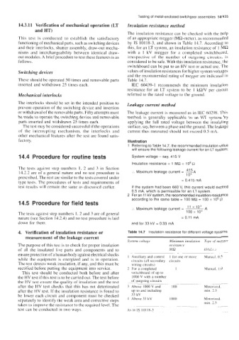
         14.3.11  Verification of mechanical operation (LT   Insulation resistance method
                and HT)
                                                       The insulation resistance can be checked with  the help
         This  test  is  conducted  to  establish  the  satisfactory   of an appropriate megger (MQ-meter), as recommended
         functioning of mechanical parts, such as switching devices   by  IS  101 18-3, and shown in Table  14.7. According  to
         and their interlocks, shutter assembly, draw-out mecha-   this, for an LT  system, an insulation resistance of  1 MR
         nisms  and  interchangeability  between  identical  draw-   with  a  1  kV  megger  for  a  completed  switchboard,
         out modules. A brief procedure to test these features is as   irrespective  of  the  number  or  outgoing  circuits,  is
         follows.                                      considered to be safe. With this insulation resistance, the
                                                       switchboard can be put to an HV test or actual use. The
         Switching devices                             values of insulation resistances for higher system voltages
                                                       and the recornmended rating of megger are indicated in
         These should be operated SO times and removable parts   Table  14.7.
         inserted and withdrawn  25 times each.          IEC  60439- 1  recommends  the  minimum  insulation
                                                       resistance  for  an  LT  system  to  be  1  kR/V  per  circuit
         Mechanical interlocks                         rderred  to the rated  voltage to the ground.
         The interlocks should be set in the intended position to   Leakage current method
         prevent operation of the switching device and insertion
         or withdrawal of the removable parts. Fifty attempts must   The leakage current is measured as in IEC 60298. This
         be made to operate the switching device and removable   method  is  generally  applicable  to  an  HT  system  by
         parts  inserted and withdrawn 25 times each.   applying  the  full  rated  voltage  between  the  insulating
          The test may be considered successful if the operations   surface, say, between a phase and the ground. The leakage
         of  the  interrupting  mechanism,  the  interlocks  and   current thus measured  Fhould not exceed 0.5 mA.
         other mechanical features after the test  are found satis-
         factory.                                      Illustration
                                                         Referring to Table 14.7, the recommended insulation value
                                                         will ensure the following leakage current for an LT system:
         14.4  Procedure for routine tests               System voltage  - say, 415 V
                                                         Insulation resistance = 1 MR = lo6 (2
         The  tests  against  step  numbers  1,  2  and  3  in  Scction         41 5
         14.2.2 are of  a general  nature and no  test procedure  is   :.  Maximum leakage current  =  -A
                                                                                10
         prescribed. The rest are similar to the tests covered under
         type tests. The procedures  of tests and requirements  of            = 0.415 mA
         test  results will  remain the same as discusscd carlicr.   If the system had been 660 V,  this current would exceed
                                                         0.5 mA, which is  permissible for an LT system.
                                                         For an 11 kV system, the recommended insulation resistance
                                                         according to the same table = 100 MR = 100 x  lo6 !J
         14.5  Procedure for field tests
                                                         :.  Maximum leakage current =   ii xi03  A
         The tests against step numbers  1, 2 and 3 are of general              100 x  106
         nature (see Section  14.2.4) and no test procedure is laid           = 0.11 mA
         down for them                                   and for 33 kV = 0.33 mA
         4.  Verification of insulation resistance or   Table 14.7  Insulation resistance for different voltage systems
            measurement of the leakage current
                                                       Swtem  iolrage    Minimum inrrr/utroii   Tipe of  mrgger
         The purpose of this test is to check for proper insulation      re,ic.tance
         of  all  the  insulated  live  parts  and  components  and  to   MR  -~        kV(dc  J
         ensure protection of a human body against electrical shocks   1  Auxiliary  and Lontrol   I  for one or inore   Mdnudl. 0 5   ~
         while  the  equipment  is  energized  and is  in  operation.   circuit\  (dll  secondary  circuits
         The test detects weak insulation, if any, and this must be   wiring circuits)
         rectified before putting the equipment into service.   2  For a completed   1   Mdnud.  IO
          This test  should be  conducted both  before  and after   switchboard of  up to
         the HV test if this test is to be camed out. The test before   1000 V with a number
         the HV test ensure the quality of insulation and the test   of  outgoing circuits
                                                                            ~   ~~~        ~__~
         after the  HV test checks that  this  has  not  deteriorated   'i Above 1000 V and   I 00   Motorired.
         after the HV test. If the insulation resistance is found to   up to and including   min  25
         be lower each circuit and component must be checked   33 kV
         separately to identify the weak area and corrective steps   4  Above  33 kV   IO00   Motorized.
         taken to improve the resistance to the required level. The   ~-    ~           min  25  ~~~
         test  can be conducted in two ways.           A? in IS  I01 18-3

