
Page 460 - Industrial Power Engineering and Applications Handbook
P. 460
14/434 Industrial Power Engineering and Applications Handbook
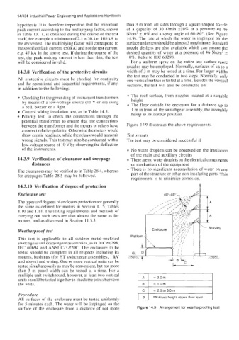
hypothesis. It is therefore imperative that the minimum than 3 m from all sides through a square shaped nozzle
peak current according to the multiplying factor, shown of a capacity of 30 Omin *lo% at a pressure of 46
in Table 13.1 1, is obtained during the course of the test N/cm' +IO% and a spray angle of 60-80". (See Figure
itself, for example a minimum of 2.1 x 50, i.e. 105 kA in 14.9). The rate at which the water is impinged on the
the above test. The multiplying factor will correspond to surface under test should be almost 5 mdminute. Standard
nozzle designs are also available which can ensure the
the specified fault current, (50 kA) and not the test current, desired quantity of water at a pressure of 46 N/cm2 *
e.g. 47 kA in the above test. If during the course of the
test, the peak making current is less than this, the test 10%. Kefer to IEC 60298.
will be considered invalid. For a uniform spray on the entire test surface more
nozzles may be employed. Normally, surfaces of up to a
14.3.8 Verification of the protective circuits width of 3 m may be tested at a time. For larger widths
the test may be conducted in two steps. Normally, only
All protective circuits must be checked for continuity one vertical surface is tested at a time. Besides the vertical
and the operational and sequential requirements, if any, sections, the test will also be conducted on:
in addition to the following:
The roof surface, from nozzles located at a suitable
Checking for the grounding of instrument transformers height
by means of a low-voltage source (1 0 V or so) using 0 The floor outside the enclosure for a distance up to
a bell, buzzer or a light.
1 m in front of the switchgear assembly, the assembly
0 Control wiring insulation test, as in Table 14.3. being in its normal position.
Polarity test: to check the connections through the
potential transformer to ensure that the connections
between the transformer and the meters or relays have Figure 14.9 illustrates the above requirements.
a correct relative polarity. Otherwise the meters would
show erratic readings, while the relays would transmit Test results
wrong signals. This test may also be conducted with a The test may be considered successful if
low-voltage source of 10 V by observing the deflection
of the instruments. No water droplets can be observed on the insulation
of the main and auxiliary circuits
14.3.9 Verification of clearance and creepage There are no water droplets on the electrical components
distances or mechanism of the equipment
0 There is no significant accumulation of water on any
The clearances may be verified as in Table 28.4, whereas
for creepages Table 28.5 may be followed. part of the structure or other non-insulating parts. This
requirement is to minimize corrosion.
14.3.10 Verification of degree of protection 3
Enclosure test
The types and degrees of enclosure protection are generally
the same as defined for motors in Section 1.15, Tables
I. 10 and 1.1 1. The testing requirements and methods of
carrying out such tests are also almost the same as for
motors, and as discussed in Section 11.5.3.
Weatherproof test
This test is applicable to all outdoor metal-enclosed Platform ~
switchgear and controlgear assemblies, as in IEC 60298,
IEC 60694 and ANSI C-37/20C. The enclosure to be F
tested should be complete in all respects including its GL D
mounts, bushings (for HT switchgear assemblies, 1 kV zz=K-r
and above) and wiring. One or more vertical units can be
tested simultaneously as may be convenient, but not more
than 3 m panel width can be tested at a time. For a
multiple unit switchboard, however, at least two vertical
units should be tested together to check the joints between
the units.
= 2.5 to 3.0 rn
Procedure I D I I
All surfaces or the enclosure must be tested uniformly Minimum heiaht above floor level
for 5 minutes each. The water will be impinged on the
surface of the enclosure from a distance of not more Figure 14.9 Arrangement for weatherproofing test