
Page 541 - Industrial Power Engineering and Applications Handbook
P. 541
Captive (emergency) power generation 16/51 5
16.9 Parallel operation I, = total load current
I, = circulating current within the two gen-
erators' circuit.
16.9.1 Theory of parallel operation
The performance of a generator varies with its operating Consider voltages E, and E2 being equal and in phase,
conditions. For instance, it is different on no-load and a condition necessary for running the two generators in
on-load when running in parallel with another generator. parallel, i.e.
Similarly, it is different when running in parallel with an
infinite bus. For a better understanding and more clarity (16.1)
we analyse below, the performance of an incoming
generator when it is required to run in parallel with another ( 16.2)
generator or with an infinite bus. Consider two generators ( 16.3)
GI and G2, operating in parallel, as illustrated in Figure
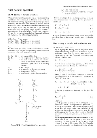
16.15, having the following parameters: In what follows we consider GI as the incoming machine
and G2 as the machine already running. connected to the
PM,, PM2 - Prime movers bus.
Z, (R, + JXd,) = Impedance of generator 1
2, iR2 + JXd2) = Impedance of generator 2 When running in parallel with another machine
Note A Performance on no-loud
For more clarity. particularly for a better illustration, we consider By changing the driving torque or power input
impedances rather than only synchronous reactances. although the
resistances. being small. are usually ignored. Suppose the driving torque of GI is increased. GI will
accelerate faster than Gz and E, will advance E?
ZL- (RL + JX,) = impedance of the load vectorially by AO, the magnitude remaining same
E,, E, = e.m.f.s generated by the two generators (Figure 16.16(a)) and
E' = residual voltage across the internal -- ( 16.4)
EI - EL =E,
circuit of the same phases of the two
generators, giving rise to circulating E, will cause a circulating current, I,. The circuit
currents. diagram is drawn in Figure 16.16(b) where
VI2 = bus voltage
.fl. f2 = frequencies of the two machines (16.5)
.fh = frequency of the bus
I,. I? = Load sharing by the two generators
Since Z, and Z2 are highly inductive. I, may be
considered lagging E, by almost 90", as shown in
Figure 16.16(a) and
-
Vh = i?~ ic 21 (we have considered the voltage
-
of the G2 bus as V,)
- --
= E? i I,. Zz
If the two generators are identical. so that Z, = Z2,
then.
v, = 2 i 16.6)
E, + E2
Inference
GI will generate an excess power compared to G,.
\ Therefore while GI will operate as ;I generator, G,.
RL Common bus at receiving power from GI, will operate as a synchronous
frequency Q motor. Since GI is overloaded compared to G?. it will
tend to retard, and G2, receiving power from GI, will
tend to accelerate. The net effect would be that both
generators will tend to synchronize on their own once
again.
b By changing the excitation (field current) In the
above case if the field excitation of the incoming
Load generator, G1, was increased, causing the terminal
voltage E, to rise to E,', so that E; > E,. Then also
Figure 16.15 Parallel operation of two generators a residual voltage, E,, would appear across the internal