
Page 536 - Industrial Power Engineering and Applications Handbook
P. 536
16/51 0 Industrial Power Engineering and Applications Handbook
I n
2
NL
R Y B N
Power diagram
For AMF panel For generator control panel
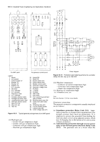
Figure 16.12 Protection and metering scheme for a smaller
Legend
1. Hooter 20. Accept P.B. rating DG set, say up to 150 kVA
2. Annunciator 21. Reset P.B.
3. Control supply 'on' 22. Engine speed raise
4. Breaker 'on' 23. Engine speed lower (iii) Machine temperature
5. Breaker 'off' 24. Breaker control switch - Collector air idout temperature high
6. Breaker 'trip' 25. Generator voltage raise - Generator field temperature high
7. D.C. ammeter 26. Generator voltage lower
8. kW meter 27. R-phase - Stator slot temperature high
9. D.C. voltmeter 28. Y-phase (iv) Bearing oil temperature high
10. A.C. ammeter 29. B-phase (v) Vibration level, etc.
11. Frequency meter 30. kWh meter
12. A.C. voltmeter 31. kVAr meter
13. Ammeter selector switch 32. Over current & ground fault Note
14. Auto/Manual switch-Sw2 relay (51 N/64) See also Section 12.8 for more details.
15. Local/Remote switch-Sw3 33. Reverse power relay (32)
16. Voltmeter selector switch 34. Overcurrent alarm relay Generator protection
17. Start-D.G. set (51~) The generator protection arrangements usually employed
18. Stop D.G. set 35. Differential relay (87)
19. Test P.B. 36. lncomer breaker feeder are as follows:
37. Lockout relay (86)
38. Under voltage relay (27) (a) Impedance protection (Relay Code 21G) Impe-
dance protection or distance back-up protection (also
Figure 16.11 Typical general arrangement of an AMF panel termed external fault back-up protection). It is
employed to protect the generator from feeding the
fault on a short-circuit on an adjacent system, which
(ii) Hydrogen gas may be hanging due to the failure of its own system
- Cooler hot gas temperature high primary protection.
- Cooler cold gas temperature high (b) Anti-motoring protection through reverse power
- Common cold gas temperature high relay or low forward power interlock (Relay Code
- Machine gas temperature high 32-G) The generator acts as a motor when the