Page 535 - Industrial Power Engineering and Applications Handbook
        P. 535
     Captive (emergency) power generation  161509
                 EOS p €OH 3 LLS 1                                               w
                           I
                     I
                                I
                     I
                                I
                           I
                                            73
                                            a,
                                            a                                     a
                     I  I   I  I   I  I     L                                     .-  L
                                            a,
                                                                                  L
                                                                                  c
                     P f l
                                                                                  al
                                                                                  Y
                                            0
                                            a,
                                                                                  2
                1444,  I                    ._                                    m
                                            m
                                            W
                                            2
                                                                                  11
                                           -                                     -
                     V
               AMF scheme (continued)
                                     Contact development                   Contact development
                                         (SW - 2)                              (SW - 3)
           Knob
          position
                                                                         Manual   Open   Close
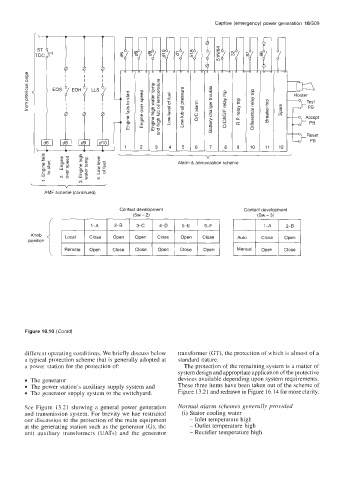
         Figure 16.10  (Contd)
         different operating conditions. We briefly discuss below   transformer (GT), the protection of which is almost of a
         a typical protection scheme that is generally adopted at   standard nature.
         a power station for the protection of           The protection of the remaining system is a matter of
                                                       system design and appropriate application of the protective
          The generator                                devices available depending upon system requirements.
          The power station's  auxiliary supply system and   These three items have been taken out of the scheme of
          The generator supply system to the switchyard.   Figure 13.21 and redrawn in Figure 16.14 for more clarity.
         See Figure  13.21 showing a  general  power generation   Normal  alarm schemes generally provided
         and transmission  system. For brevity we hae restricted   (i) Stator cooling water
         our discussion to the protection of  the main equipment   - Inlet temperature high
         at the generating  station such as the generator (G), the   - Outlet temperature high
         unit  auxiliary  transformers  (UATs)  and  the  generator   - Rectifier temperature high
     	
