
Page 530 - Industrial Power Engineering and Applications Handbook
P. 530
16/504 Industrial Power Engineering and Applications Handbook
which is normally selected for only 0.8 x kVA (kW = p.f.
'Yb
x kVA). At higher p.f.s, while the active component OA
of the revised current OA" remains the same as at 0.8
p.f., the generator will draw a lower current at I& and
operate underloaded, while the engine will be fully loaded
and the DG set will deliver its optimum rated output. For
a resistive load of 100 kW, for instance, operating at
unity p.f., a generator rated for 100 kVA is not suitable
because the kW rating of the engine for a 100 kVA set
@= 0.8 will be only 0.8 x 100 i.e. 80 kW.
:. The DG set (at least the engine) for such a load must
Y be selected for 100 x 1, i.e. 100 kW or 125 kVA.
(i) p.f. - unity (ii) p.f. - 0.8 lagging
VAvR - Marginally more VAvR - Slightly more
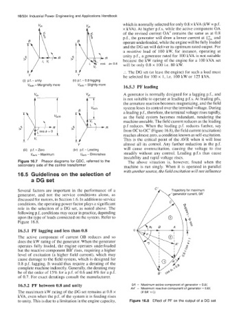
16.5.3 PF leading
A generator is normally designed for a lagging p.f., and
i"7 the armature reaction becomes magnetizing, and the field
is not suitable to operate at leading p.f.s. At leading pfs,
a leading p.f., therefore, the terminal voltage rises rapidly,
I system loses its control over the terminal voltage. During
VAVR as the field system becomes redundant, rendering the
I
/ d- machine unstable. The field current reduces as the leading
p.f reduces. When the leading p.f. reduces further, say
from OC to OC' (Figure 16.8), the field current (excitation)
jcos@=o
I/ reaches almost zero, a condition known as self-excitation.
This is the critical point of the AVR when it will lose
Y almost all its control. Any further reduction in thc p.f.
(iii) p.f. - Zero (iv) p.f. - Leading will cause overexcitation, causing the voltage to rise
VAvR - Maximum VAvR - Diminishes steadily without any control. Leading p.f.s thus cause
instability and rapid voltage rises.
Figure 16.7 Phasor diagrams for QDC, referred to the The above situation is, however, found when the
secondary side of the control transformer machine is run singly. When it is operated in parallel
with another source, the field excitation will not influence
16.5 Guidelines on the selection of
a DG set
Several factors are important in the performance of a Trajectory for maximum
generator, and not the service conditions alone, as generator current, OA'
discussed for motors, in Section 1.6. In addition to service
conditions, the operating power factor plays a significant
role in the selection of a DG set, as noted above. The
following p.f. conditions may occur in practice, depending
upon the type of loads connected on the system. Refer to
Figure 16.8.
16.5.1 PF lagging and less than 0.8
The active component of current OB reduces and so
does the kW rating of the generator. When the generator
operates fully loaded, the engine operates underloaded
but the reactive component BB' rises, requiring a higher
level of excitation (a higher field current), which may
cause damage to the field system, which is designed for
0.8 p.f. lagging. It would thus require a derating of the
complete machine indirectly. Generally, the derating may
be of the order of 15% for a p.f. of 0.6 and 8% for a p.f.
of 0.7. For exact deratings consult the manufacturer.
16.5.2 PF between 0.8 and unity OA - Maximum active component of generator = O.S/,
AA - Maximum reactive component of generator = 0.6/,
The maximum kW rating of the DG set remains at 0.8 x (if OA = /,)
kVA, even when the p.f. of the system it is feeding rises
to unity. This is due to a limitation in the engine capacity, Figure 16.8 Effect of PF on the output of a DG set