
Page 528 - Industrial Power Engineering and Applications Handbook
P. 528
16/502 Industrial Power Engineering and Applications Handbook
And an improved loading = 49325' + 4703'
m = 10 444 kVA
*
r
ln
as against 14 346 kVA
9325
and improved p.f. = -
10 444
= 0.89 as against 0.65
It is, however, recommended for better control and machine
utilization that when the load's demand is for constant-speed
operation, this must be met through separate synchronous
motors at unity p.f. and the p.f. must be improved separately
m
'2 through synchronous condensers with variable field excitation.
If the synchronous condensers are employed only to improve
the system p.f. from 0.65 to, say, 0.9 lagging, then the rating
2 of the machines can be determined as follows:
k Total active load = 9325 kW
c9
0
r-
d
9325
:. kVA at 0.9 p.f. lagging = -
0.9
= 10 361 kVA
And reactive kVAr = 10 361 sin cos-' 0.9
T 5415
= 10 361 x 0.436
2 1 :. Compensation is required for
kVAr
= 451 7 kVAr
= 10903-4517
= 6386 kVAr
785
kVAr Then the kVA of the synchronous condensers, operating at
-A 0.1 p.f. leading and having an efficiency of 98%
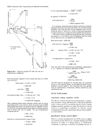
Figure 16.4 Improving system PF with the use of a - 6386 (Figure 16.5)
synchronous condenser 0.98 sin cos-'0.1
- 6386
0.98 x 0.995
Draw the phasor diagram for the actual load also at 12 500
h.p. at 0.65 p.f. = 6549 Say, 6550 kVA
.. Active load = 12 500 x 0.746 The AVR may be designed for variable duty, for automatic
control of the reactive power, to the required level through
= 9325 kW feedback control systems. The machines will now operate
only as synchronous condensers without performing any
9325
and kVA = ~ mechanical duty.
0.65
= 14 346 kVA
16.3.4 Field system
and reactive load, kVAr = 14 346 sin cos-' 0.65
= 14 346 x 0.76 Automatic voltage regulator (AVR)
= 10 903 kVAr (lagging) This device controls the generator and maintains a steady-
state armature voltage automatically within the predefined
After replacing these large induction motors with as many
oversized synchronous motors, while the active load at 9325 limits. It also serves to control the reactive kVAr loading
kW remains the same, the reactive load of induction motors during a parallel operation or when the machine is being
at 785 kVAr will be eliminated and instead a leading reactive used as a synchronous condenser for reactive power
load of 5415 kVAr will be added. The net compensation compensation through a quadrature droop control (QDC)
therefore will be as noted below.
= 785 + 5415
= 6200 kVAr Quadrature droop control (QDC)
leaving an uncompensated reactive load This is a scheme introduced in the AVR circuit to adjust
the reactive power (kVAr) of a machine during a parallel
= 10 903 - 6200 operation or when it is being used as a synchronous
= 4703 kVAr condenser. It prevents a reactive circulating current, I,,